Motorhome Inverter Wiring Diagram Wiring Diagram
Disconnect from any shore power and generators and isolate your battery bank before you begin. Step 1: Identify your priority AC circuits. These will be powered by the inverter when you are off-grid. Step 2: Install your inverter, with an AC distribution box with individual circuit RCDs for each priority circuit.

Rv Inverter Charger Wiring Diagram Circuit Diagram
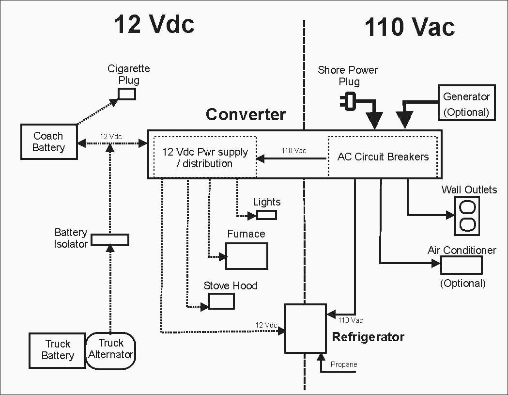
Most RV manufacturers install a "converter" into the RV's electrical system so that your auxiliary battery will charge while you are plugged into shore power - it converts AC power to DC power.

Inverter Battery Wiring Diagram NOCHAPUNYER
Introducing the Interactive RV Wiring Diagram - the ultimate tool for designing electrical systems for RVs, campervan conversions, skoolies, travel trailers & motorhomes. Designed to provide a comprehensive and efficient solution to the complexities of the wiring systems in campers. Automatically Create Your Bespoke RV Wiring Diagram

Inverter Charger Wiring Diagram
The 3-way changeover switch shown in the below diagram is a manual changeover switch of a specific company, model number is written on the diagram. You can use any changeover switch and wire it up on the same lines. Here is a schematic diagram in PDF and this is a wiring diagram in PDF. Charging the Batteries from AC Shore Line or AC Generator

RV Inverter Wiring Diagram (RV Electricity Explained) Justdownsize
Watch on Inverter Wiring Process The inverter, a gadget designed to transform Direct Current (DC) to Alternating Current (AC), presents an intriguing subject. This discussion takes the form of a straightforward illustration where an inverter interfaces with a battery bank.
3 Battery Wiring Diagram Rv Wiring Diagram and Schematic
Today we show you our EASY RV inverter setup to power ALMOST your entire RV. We use a Renogy 2000 watt pure sine wave inverter that allows us to plug our RV.

Motorhome 30 Amp Rv Wiring Diagram Easy Wiring
RV inverter wiring diagram (RV electricity explained) By Elaine Knight Page last updated: 13/04/2021 | Next review date: 13/04/2023 In this article, we give you an RV inverter wiring diagram, we explain how to instal an RV inverter and help you choose the best one for your needs. RV inverter wiring diagram
Basic Rv Battery Charger Options Rvshare Rv Converter Charger
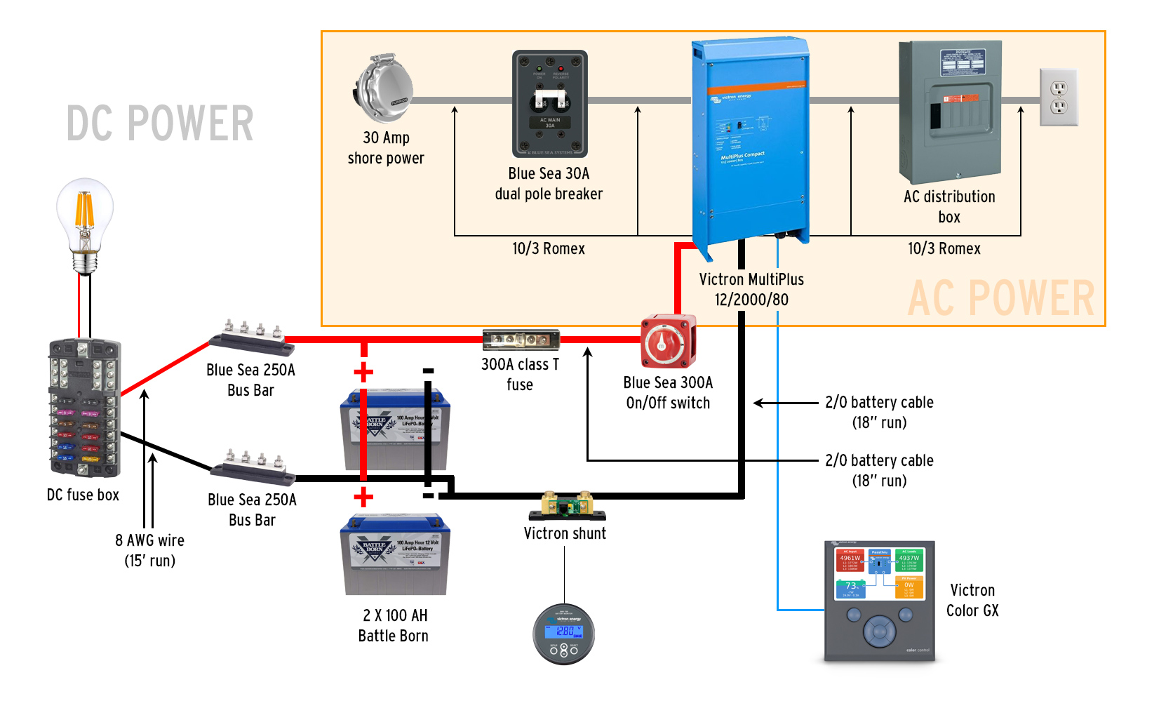
The RV wiring diagram with inverter typically includes the battery bank, inverter, charger/converter, and various other components such as fuses, breakers, and switches. The battery bank is the heart of the system, providing the DC power needed to run the inverter. The inverter then converts this DC power into AC power, which can be used to.

RV Inverter Best Options All About RVs
#1. Make Certain You Purchase A Compatible Inverter. You must get a model that suits your requirements since not all inverters are compatible with all RV electrical systems. In our purchasing guide, we go into greater depth, but in a nutshell, watch out for: It produces the proper voltage (110v or 240v) Needs the proper input voltage (12v or 24v),

Inverter Wiring Diagram For Rv
Enter the power inverter - a handy device that converts electricity from a 12V battery system to 110V "household" electricity that can power things like TV's, fans, and other regular appliances. What We're Installing The two major components in this install are the power inverter and a power meter so we can see how electricity is being used.

Keystone Rv Wiring Diagram Wiring Diagram
Use the RV electrical diagram we made below to get an understanding of what powers what and to learn how an RV electrical system works. Contents show Understanding AC vs DC Power RVs are powered by two electrical systems, AC and DC. AC, also called alternating current, is what typically powers a regular brick-and-mortar home.

RV Inverter Wiring Diagram (RV Electricity Explained) Justdownsize
Remove the converter. Create a mounting location for the new inverter charger. Run the AC wiring from the inverter to the breaker panel. Connect the AC side of the inverter. AC in (coming from the shore power) AC out (going from inverter to the breaker panel) Connect the DC side of the inverter. To the battery bank.

Schematic Diagram For Ac Dc Inverters
If you have trouble finding suitable wire for your RV inverter install, automotive battery cable or jumper cables are readily available in 4, 6, and 8 AWG (American Wire Gauge). Welding cable comes in larger sizes, but is expensive as many times you have to buy a whole spool.
Rv Electrical Diagram / Rv Inverter Wiring Diagram Wiring Diagram
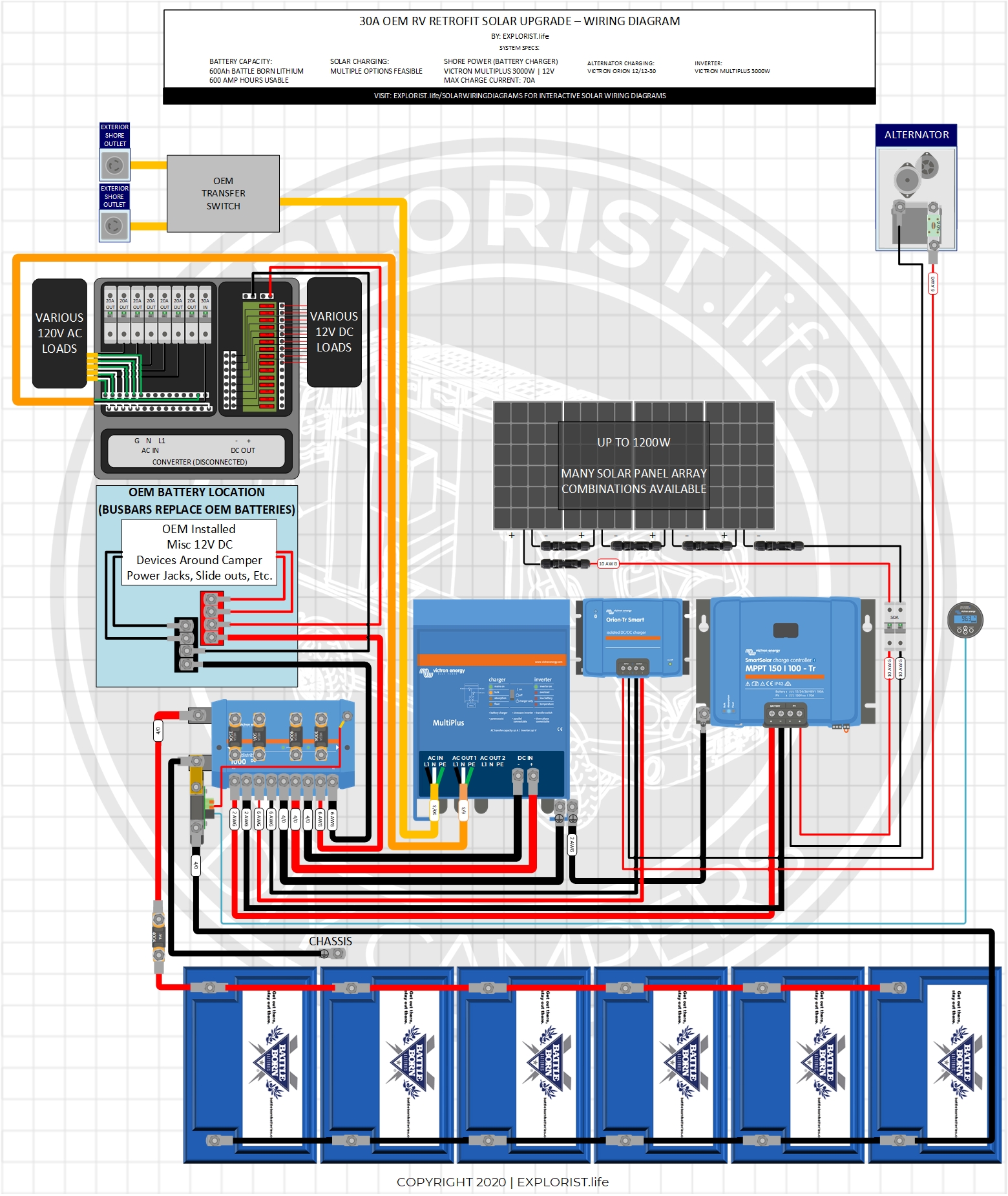
Nov 15th 2022 Typical RV Wiring Diagram Explained: Any Better Solution Available? If you're looking for a self-build RV wiring diagram that works in Canada, you've found it. This diagram represents one of the most common setups in Canada and it is designed for a 2kWh solar power system, which is sufficient for a couple's or two friends' journey.
Rv Inverter Wiring Diagram Cadician's Blog
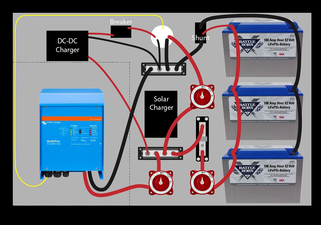
Diagram Of An RV Inverter The most common wiring schematic for an RV inverter may be seen here. But before you start, we urge you to consider the following crucial advice for installing an RV inverter: Always place a fuse in the event of a short circuit between the battery and the power inverter so that the installation is safeguarded.

Sub Panel / Inverter Wiring Technical Tips and Tricks Escapees
Inverters for RVs add a tremendous amount of flexibility and functionality. Today we install the Victron MultiPlus a Hybrid Inverter. I show how to install i.