
Trailer Breakaway System Wiring
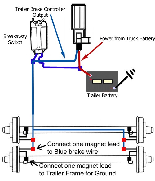
Step 1: Route the Wires When installing the breakaway switch, insert the wires from it to the junction box, as shown in the picture below. The wires will connect as follows: The blue wire will connect with the other blue wires (break leads) - see Step 5 when wiring at the junction box.

trailer breakaway switch wiring diagram Wiring Diagram
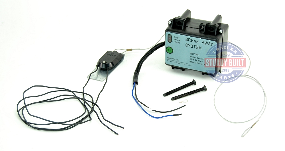
1. Splice one blue wire of the Break-Away Switch to the electric brake wire coming from the trailer side connector (A - see diagram on next page). 2. Connect other blue wire of Break-Away Switch to the blue wire (labeled "Brake") from the Break-Away box (B). (Note: Blue wires are interchangeable on the Break-Away Switch.) 3.
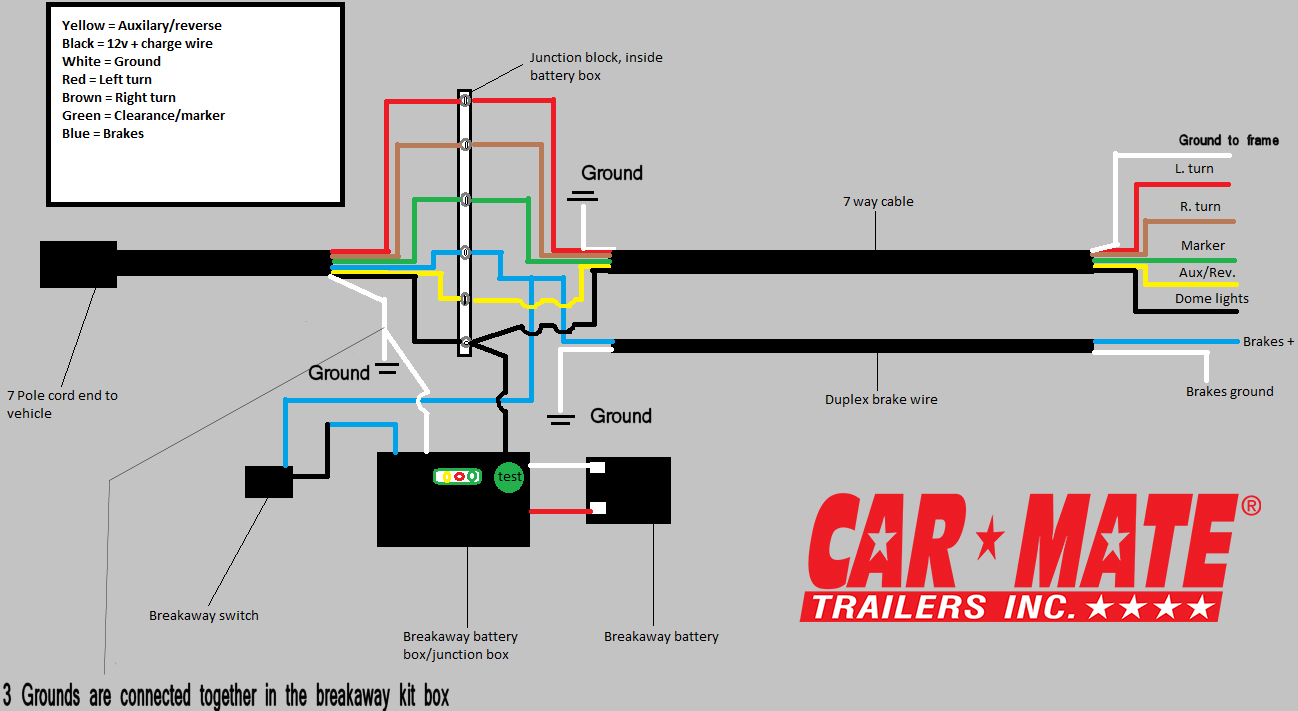
Technical Support Car Mate Trailers, Inc
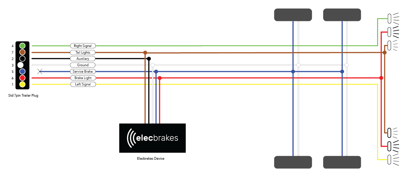
7-Way Connectors Aside from the three main lighting functions, additional pins for electric brakes, a 12 volt "hot" lead, and backup lights are available. There are two types of 7-way connectors. One has flat pins, which are often referred to as blades. The other has round pins. The round pin style is very rare.
Trailer Breakaway Battery Wiring Diagram My Wiring DIagram
The following article will describe how to: Mount a trailer breakaway kit Wire the breakaway kit Details Hopkins, Tekonsha, with and without a charger Attach to a vehicle Before the breakaway kit installation begins, you will need: Breakaway kit - includes a breakaway switch and a battery contained in a mounting box Electric trailer brakes
Electric Brake Wiring Grounding Out
We have a online diagram that will help you understand how the break away system is wired into your trailer. It is actually a simple installation. The system splices into the existing trailer wiring. The break away box will have 3 wires coming out of it, a black, a white, and a blue wire.

Trailer Wiring Schematic 7 Way Free Wiring Diagram
The trailer breakaway system wiring diagram will provide detailed instructions on how to connect the components of the system. This includes the breakaway switch, wiring harness, and power source. It's important to follow the diagram carefully and ensure that all the connections are correct.
Trailer Breakaway Kit Wiring Diagram General Wiring Diagram
A trailer breakaway switch wiring diagram will show you how to connect the wires from the breakaway switch to the electrical components on your trailer. The wiring diagram usually includes a connector pinout and a color-coded wire diagram to make it easier to connect the wires.

How to Test a Trailer Breakaway Switch PopUpBackpacker
On this page (typically below the product links) there is a helpful link section that will have the install instructions fo the Hopkins Breakaway kit part # 20400 that you referenced. I also attached an install video that shows the kit installed as well as a diagram for trailer breakaway wiring as well. The white wire is the ground wire.

Electric Trailer Brakes Wiring Schematic Trailer Brake Wire
In this video, I replace my old worn looking trailer breakaway safety switch with a new one. I explain the wiring and test it.The breakaway switch is there i.
Haulmark Trailer Breakaway Brake Wiring Diagram
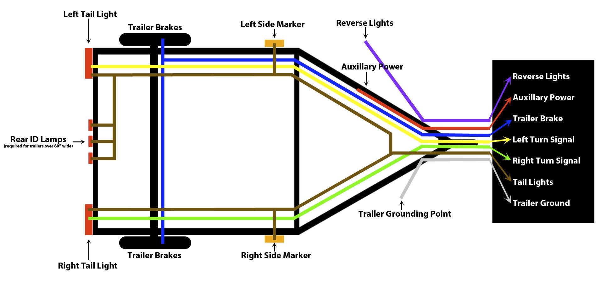
1 . White = Ground (See White Wire Notes below.) 2 . Brown = Tail Lights, Side Markers and Running Lights (See Brown Wire Notes below.) 3 . Yellow = Left Turn Signal & Left Brake Light 4 . Green = Right Turn Signal & Right Brake Light Please see the Trailer Wiring Diagram and Connector Application Chart below.
Breakaway Switch Diagram My Wiring DIagram
7-ways are some of the most common harnesses found on trailers. 7-ways provide the required running lights, turn signals, brake lights, and ground for the trailer. In addition, they provide three additional pins for a 12V hot lead, electric brakes, and reverse lights. Trailer wiring can be one of the most intimidating components of your towing.
harbor freight led trailer lights wiring diagram Wiring Diagram and
An Overview of Trailer Breakaway System Wiring Diagrams When it comes to hauling a trailer, safety is paramount. One of the key components of a safe towing setup is the trailer's breakaway system. This system engages brakes on the trailer if the towing vehicle and trailer become disconnected, helping to prevent runaway trailers.
Trailer Breakaway Box Wiring Diagram Wiring Diagram
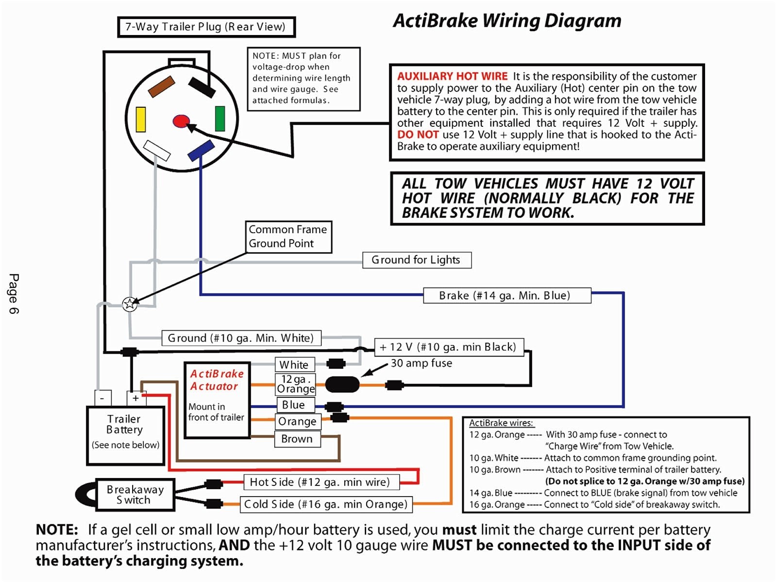
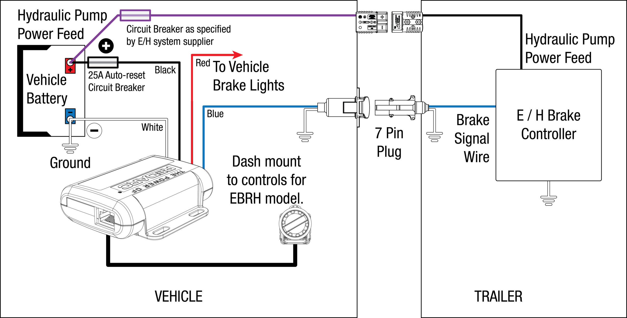
Generic Electric Brake Wiring Diagram for Dash Mounted Brake controller & Trailer mounted TAP Brakemaster Electric breakaway kit. Note: US Dept. of Transportation requires that trailers equipped with brakes have a trailer break away system for activation of the trailer brakes, in the event that the trailer should become detached from the tow vehicle during highway travel.
Breakaway Switch Diagram for Installation on a Dump Trailer with
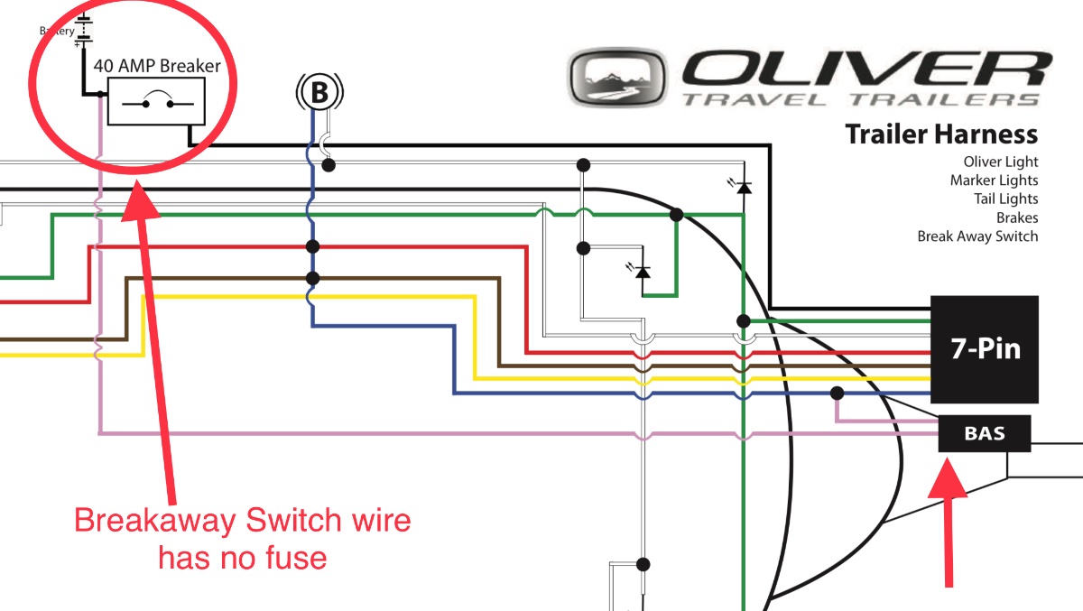
Here is a wiring diagram for your Trailer Breakaway Kit. This is typical, but check your system to be sure the wires (colors) are the same. This little bit of schematic attaches into the full trailer wiring diagram from our other article. Power to charge the battery comes from the "Aux +12V Power" wire (Usually Red, but sometimes black).
2 Wire Trailer Breakaway Switch Wiring Diagram Wiring Diagram
Convenient wiring diagram is printed on the box ; Kit includes breakaway switch, battery box, and wiring. Self Adjusting Electric Trailer Brake Kit # AKEBRK-35-SA Galvanized Trailer Hub and Drum Assembly # AKHD-545-35-G-K etrailer Trailer Wiring 7-Way Upgrade Kit w/ Junction Box # e99011 Bright Way Trailer Breakaway Kit # 3802337 It appears.

Trailer Breakaway Wiring Diagram
0 Comment The trailer breakaway switch is a crucial safety device that will help prevent an unattended trailer from causing potential harm. It's important to understand how to wire up a trailer breakaway switch, as even the slightest mistake in wiring could result in disaster.