
Contactor Wiring Diagram For 3 Phase Motor Naturalied
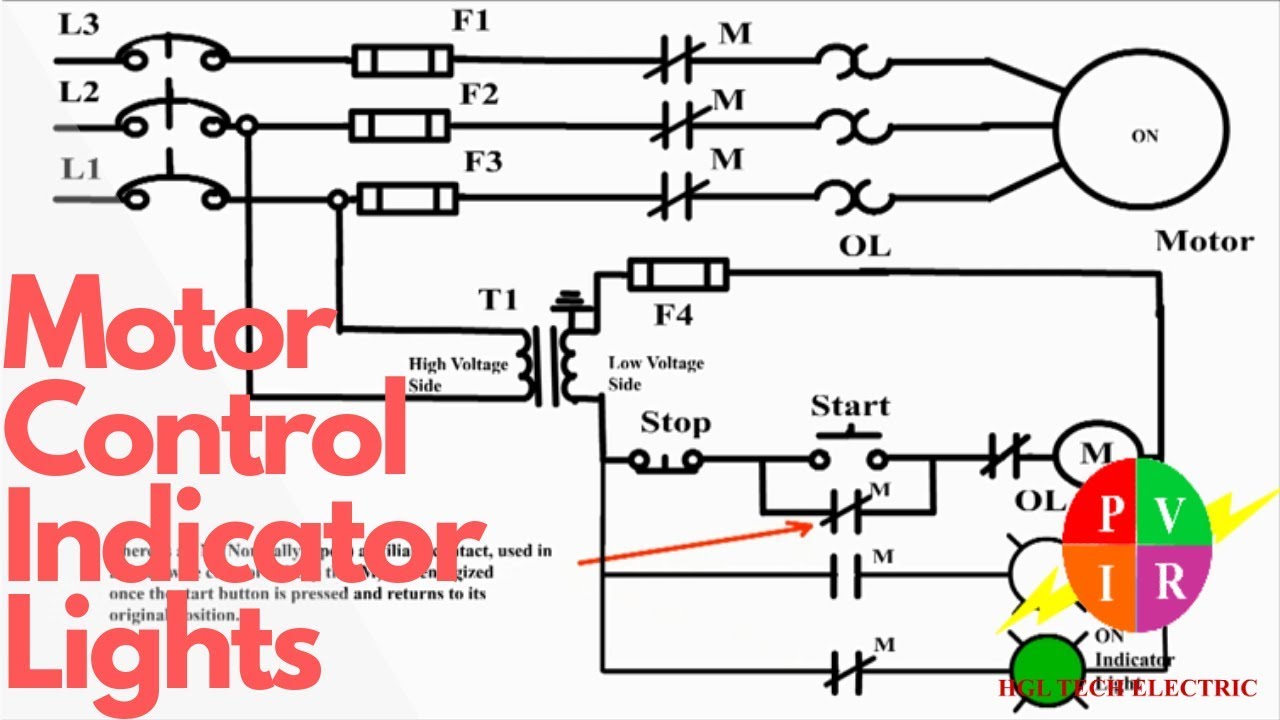
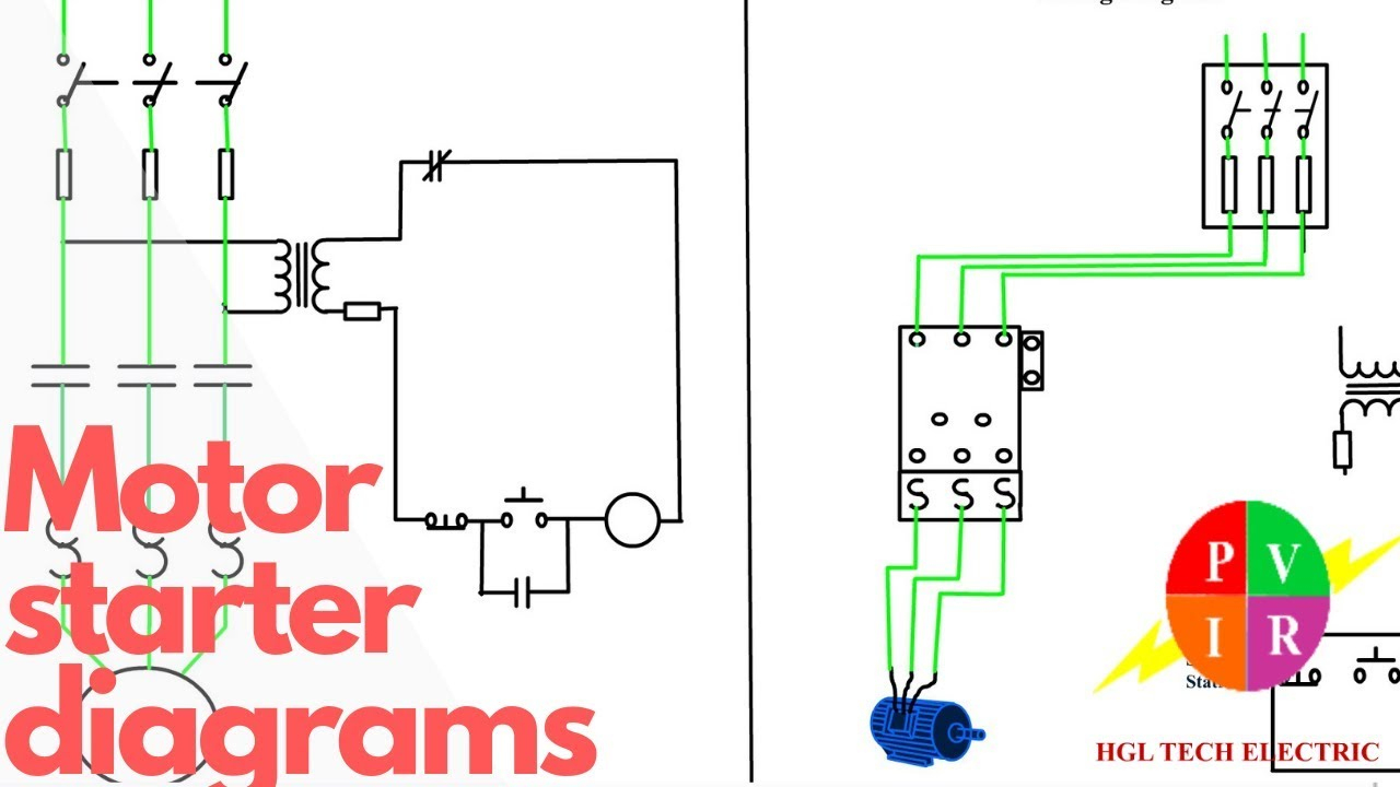
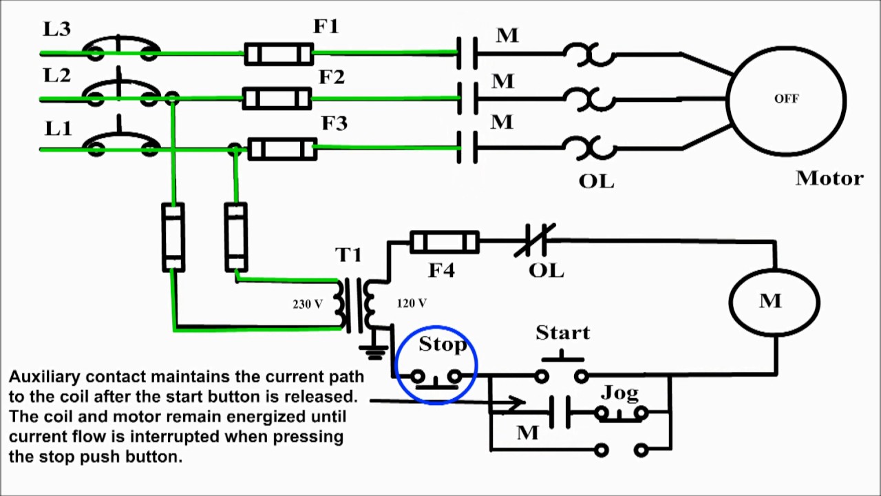
Motor contactor (or "starter") coils are typically designated by the letter "M" in ladder logic diagrams. Continuous motor operation with a momentary "start" switch is possible if a normally-open "seal-in" contact from the contactor is connected in parallel with the start switch so that once the contactor is energized it maintains power to itself and keeps itself "latched" on.
Start Stop Motor Control Schematic Diagram
Typical Wiring Diagrams For Push Button Control Stations Start-Stop Control Wiring Diagrams 4 SINGLE STATION - MAINTAINED CONTACT PUSH BUTTONS t-----t L1 UNDERVOLTAGE RELEASE O.L. L2 i-c-[ START I I1 I 1 I I lr\ 0 I /;: $77 I I I I I I; STOP! L-m,----e- 1 The START button mechanically maintains the contacts that take the place of hold-in contacts.
Motor Overload Circuit Diagram
Motor Contol Language of Control Circuit diagrams communicate information quickly and efficiently. Every trade and profession has its method of communicat-ing ideas and information quickly and efficiently. In addition to the terminology shown in the glossary of this text, dia-grams play a vital role of communication in electrical cir-cuits.

Stop Start Motor Control Circuit Diagram
start stop motor control circiuit and wiring installation.part two

Sequence Controls for Motor Starters
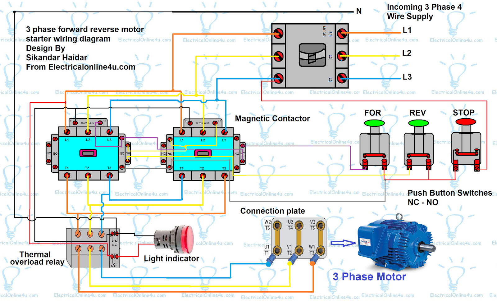
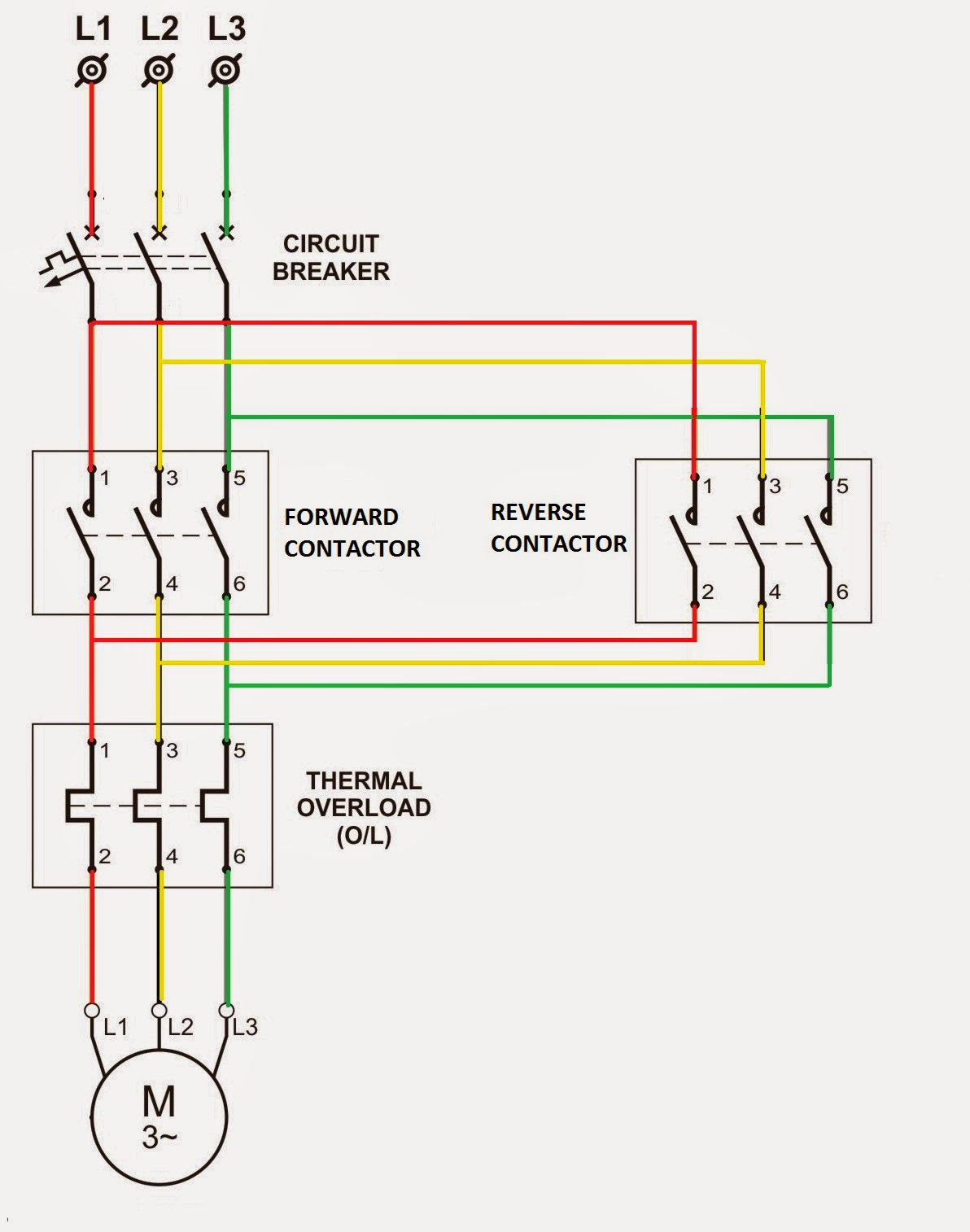
A start-stop control diagram is used when a motor needs to be started and stopped manually. It typically consists of a start button, stop button, and a set of contacts that control the motor's operation. On the other hand, a forward-reverse control diagram is used when a motor needs to change direction.
Start Stop Diagram For Motor
1. Introduction3 1.1 Equipment overview 5 2. General12 2.1 Graphical symbols with nomenclature for circuit diagrams 12 2.2 Marking and identification of terminals of contactors and associated overload relays 18 2.3 Terminal markings for electric motors 21 3.
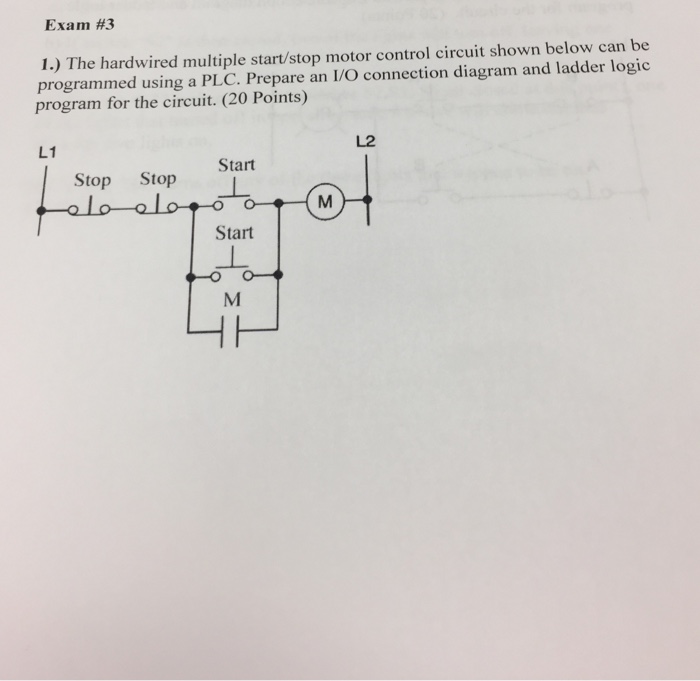
Solved The hardwired multiple start/stop motor control
To stop either circuit (forward or backward), we require some means for the operator to interrupt power to the motor contactors. We'll call this new switch, Stop:
Motor Starter Wiring Diagram Start Stop Cadician's Blog
This video explains the basics of a simple start stop motor control circuit.
Start Stop Motor Relay Circuit video Dailymotion
Start Stop Jog Circuit | Motor Control Circuit Diagram Jog Circuit Definition The jog circuit is important to create a circuit that will allow the operator to momentarily energize the circuit without the need of pressing the stop pushbutton.
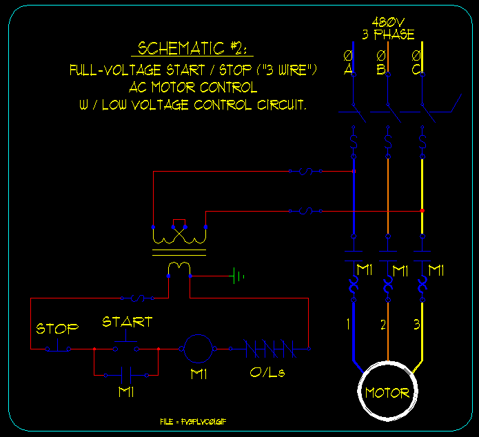
Basic Start/Stop AC Motor Control Schematics under Repositorycircuits
Standard duty "START-STOP" stations are provided with the connections "A". shown in the adjacent diagram. This. connection must be removed from all but one of the "START-STOP" stations used. Heavy duty and oiltight push button stations can also be used but they do not. have the wiring connection "A", so it must.
3 Phase Contactor Wiring Diagram Start Stop Pdf Wiring Harness Diagram
Manual and Automatic Controls Mostly referred to as hand-off- auto, a two wire control system is constructed to facilitate either the manual operation of a load by maintaining power to the coil through a toggle switch as seen in the diagram below, or automatically controlled by a control device similar to a liquid level switch.
Two Wire & Three Wire Motor Control Circuit Motor Control Circuit
A start stop schematic diagram is a graphical representation of a circuit that controls the starting and stopping of a motor. It is commonly used in industrial settings to illustrate the wiring and components necessary for operating a motor using start and stop buttons. The diagram typically includes symbols representing the motor, start button.

How to Make Three Phase Motor With Start and Stop Wiring Diagram
Control Circuit Diagram Schematic Control Wiring Diagram Traditional Single-Location Control Before discussing multi-location control, let's briefly review the conventional single-location motor control. In a basic setup, a single start-stop station is directly wired to the motor starter.
[DIAGRAM] 3 Phase Start Stop Station Wiring Diagram FULL Version HD
Find the deal you deserve on eBay. Discover discounts from sellers across the globe. We've got your back with eBay money-back guarantee. Enjoy Start stop you can trust.

Industrial Motor Control General Principles of Motor Control
Lucidchart's Flow Diagram Software Is Quick & Easy To Use. Free 7-Day Trial. Our Diagram Creator Makes It Easy To Share and Edit Your Diagrams—With Anyone, Anytime.
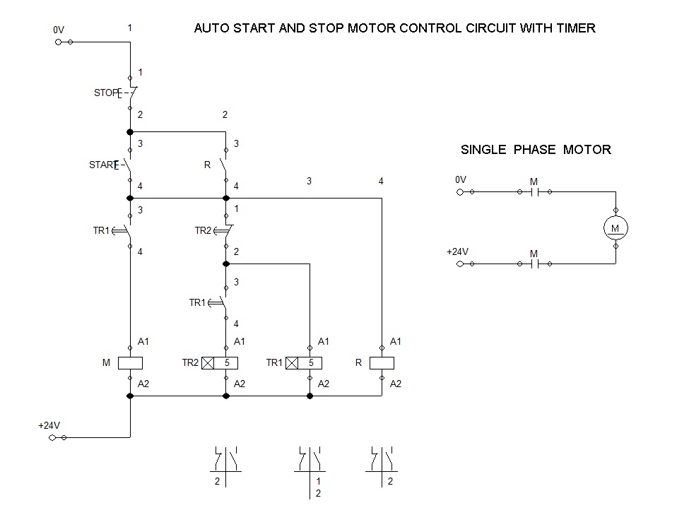
Across The Line Starter Auto Start and Stop Motor Control
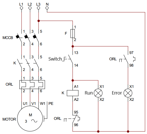
Circuit diagram This diagram is the most basic circuit that uses a switch to control a motor through a contactor. When the state switch is open, the motor will not work. When the state switch is closed, the motor will start to rotate. 2 wire control circuit