Wiring Diagram 7 Pin Trailer Connector
Trailer Wiring Connectors Various connectors are available from four to seven pins that allow for the transfer of power for the lighting as well as auxiliary functions such as an electric trailer brake controller, backup lights, or a 12V power supply for a winch or interior trailer lights.
Wiring For 7 Pin Trailer Plug
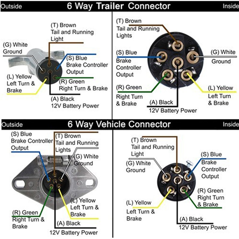
5-Way Connectors 5-Way connectors are available allowing the basic hookup of the three lighting functions (running, turn, and brake) and, besides the ground, one pin is available to provide support for another function. Typically the 5-Way Flat is used for trailers with surge brakes or hydraulic brakes.
6 Pin To 7 Pin Trailer Wiring Diagram / 2 7 pin trailer connection wiring diagram. Wiki Blog 33
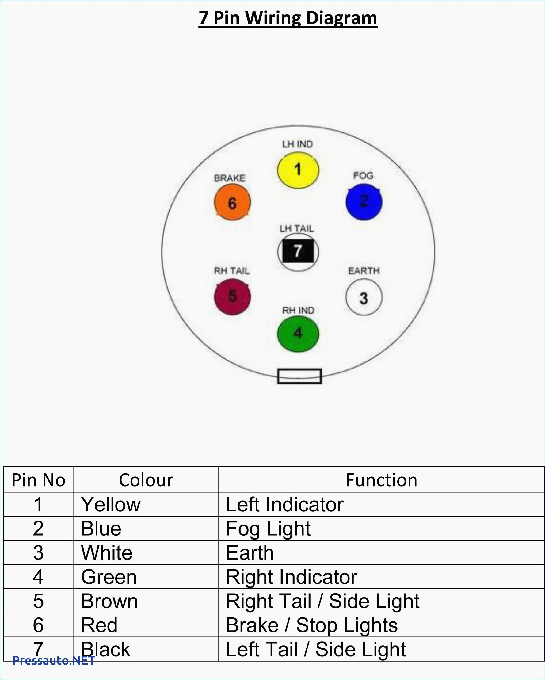
Understanding the wiring diagram is essential for anyone looking to install a 7-pin trailer plug. Each pin represents a specific function, such as tail lights, brake lights, or turn signals. By following the wiring diagram, you can easily connect the corresponding wires from your vehicle's electrical system to the trailer plug.

Wiring Diagram For A Trailer Connector
7 Way Plug Wiring Diagram Standard Wiring* This is the most common (Standard) wiring scheme for RV Plugs and the one used by major auto manufacturers today. * Always test wires for function and wire accordingly. This wiring scheme is for reference only. copyright © 2001, Country Trailer Sales All Rights Reserved
7 Pin Trailer Plug Wiring Diagram Wiring Diagram
7-Way Trailer Plug Wiring Diagram | A Complete Guide By Brian Gillan December 18, 2023 7-way trailer connectors are an essential component for providing transfer of power between a towing vehicle and trailer. Proper wiring of these connectors is important for safe and successful towing.
7 Way Trailer Plug Wiring Diagram Wiring Diagram
Trailer Wiring Diagram Not sure which wires attach to what on your trailer connectors? Does one of your turn signals not work and you're not sure which wire to inspect? Check out or trailer wiring diagrams for a quick reference on trailer wiring.
Hopkins Trailer Connector Wiring Diagram Wiring Diagram
The 7-Way Trailer Plug is around 2″ diameter connector that allows an additional pin for an auxiliary 12-volt power or backup lights. It is usually used for towing heavy-duty cargo trailers, aluminum trailers, dump trailers, utility / landscape trailers, equipment trailers, open car haulers and enclosed car haulers.

Wiring A Trailer & Plug Commercial Trailers Qld Aluminium Machine
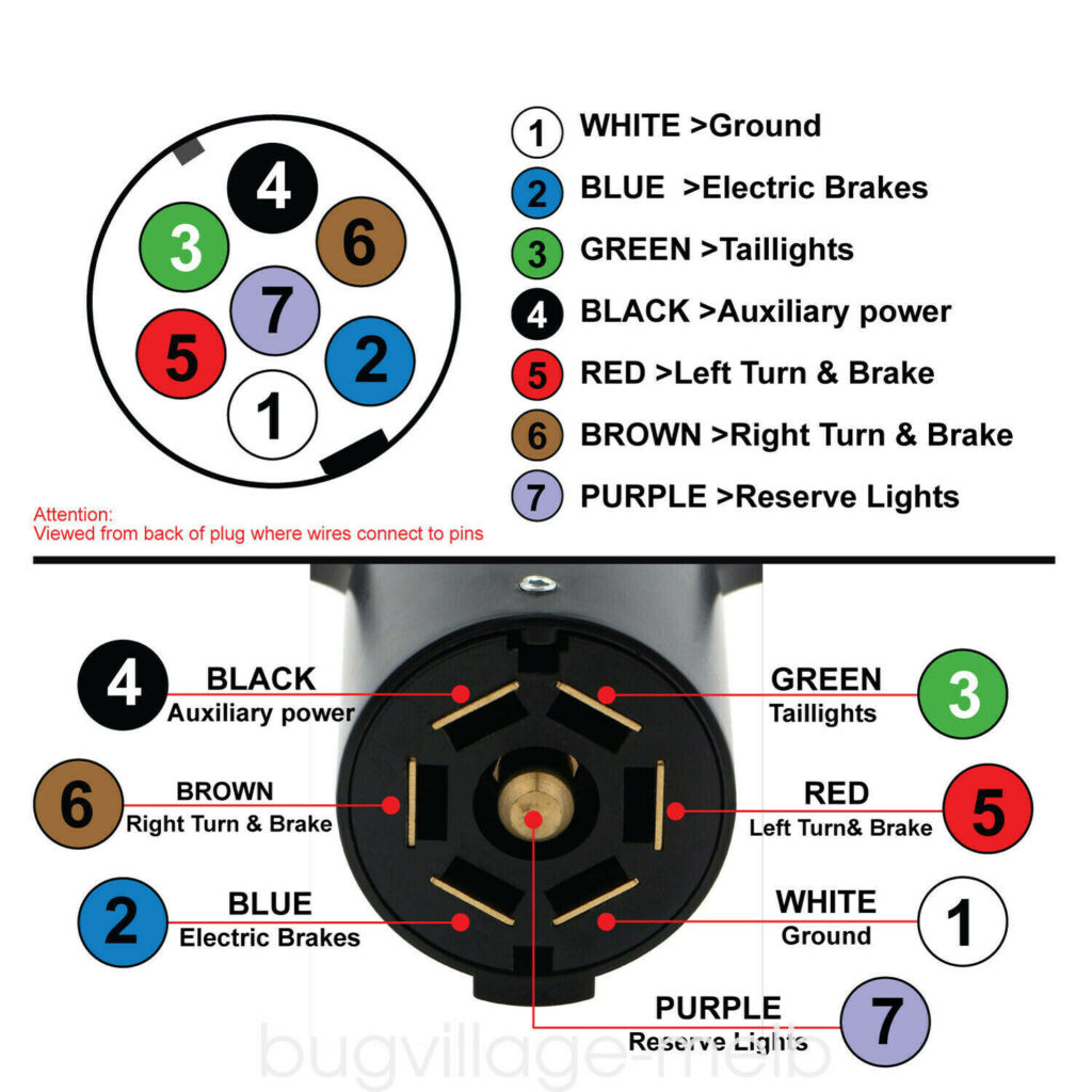
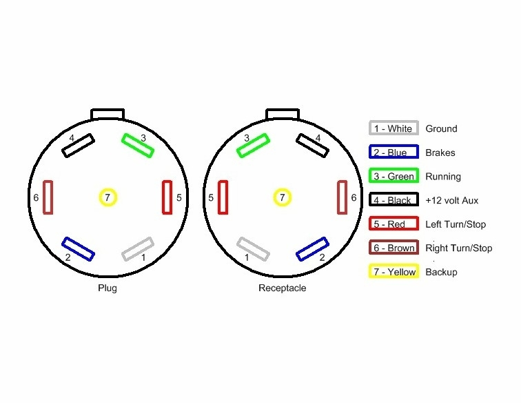
Standard Electrical Connector Wiring Diagram. NOTE: Standard wiring pictured below, viewed from the rear of connector (where wires attach). Not all trailers/vehicles are wired to this standard. The use of an electrical circuit tester is recommended to ensure proper match of vehicle's wiring to the trailer's wiring. On the 6 way plugs the.
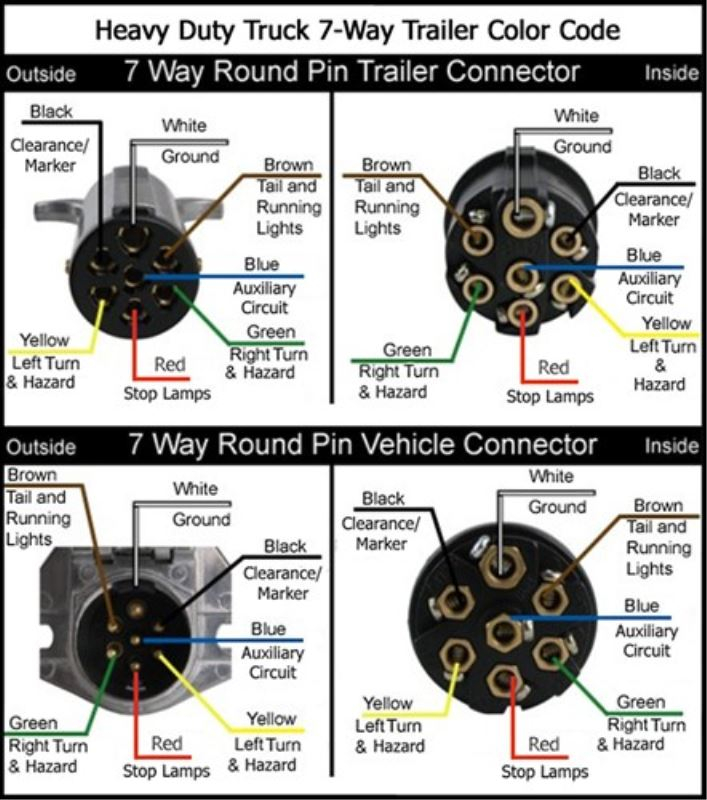
7 Way Trailer Plug Wiring Colors
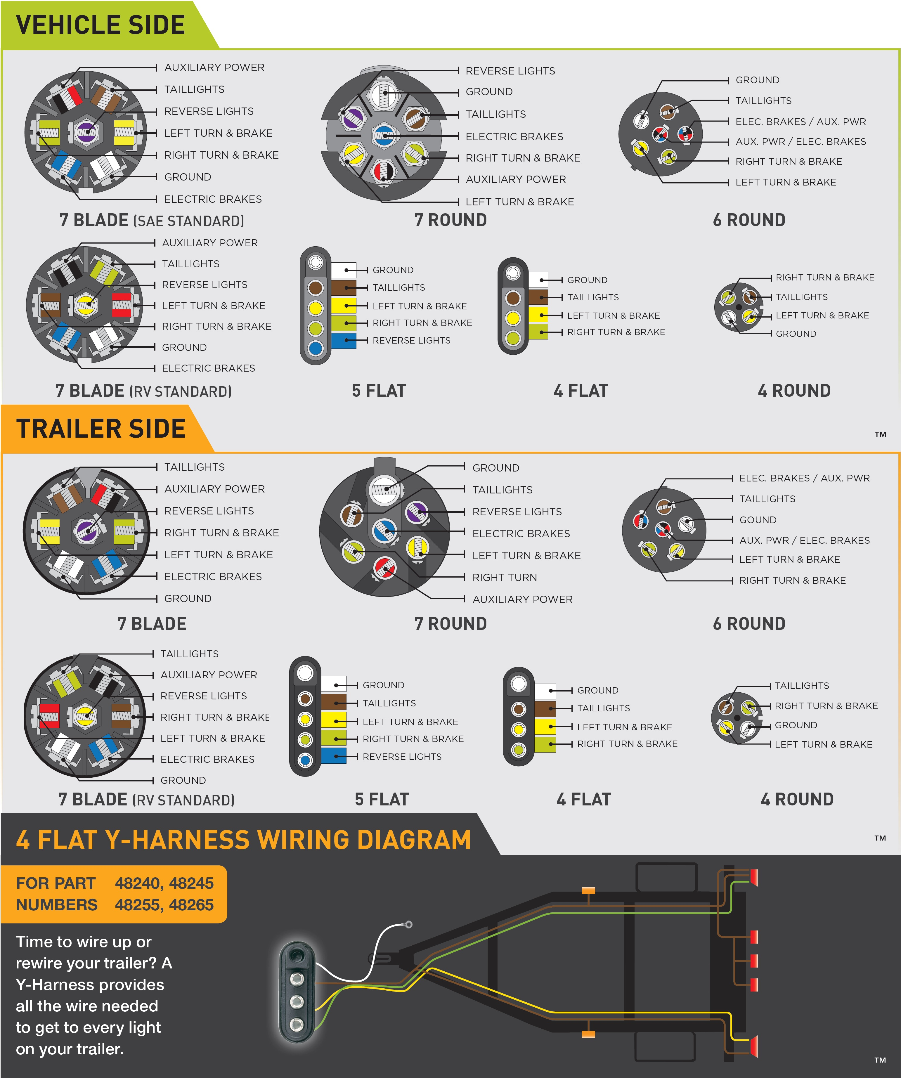
View Trailer Wiring Diagrams Here! 3 Options for Installing Trailer Wiring on Your Vehicle A. Custom wiring Vehicle-specific plug-and-play harness that requires no splicing and provides a standard trailer connector B. Splice-in wiring Taillight converter that splices into your existing vehicle wiring and provides a standard trailer connector
4 Pin Trailer Wiring Diagram 4 Pin Trailer Connector Wiring Diagram in 2020 Trailer
Not sure exactly what each wire does? The easiest way to figure it out is to use a circuit tester to confirm the function of each wire. What Size Wire Gauge is Used for a 7-Way Wiring Harness? The minimum suggested wire size for a 7-way trailer plug is 16 gauge for the turn signals, brake lights, reverse lights, and running light wires.

6 Pin Trailer Connector Wiring Diagram Free Wiring Diagram
If you have a 4-way plug, add a 5-way with a 4-to-5-way adapter Use a circuit tester to confirm wire function. Step 2: Connect Ground to Vehicle Frame Just like we did on the trailer, we now have to connect the ground on the vehicle side. Attach the white ground wire to a clean, bare metal surface on the vehicle frame.

Ellie Wired Wiring Diagram For A 4 Pin Trailer Connector
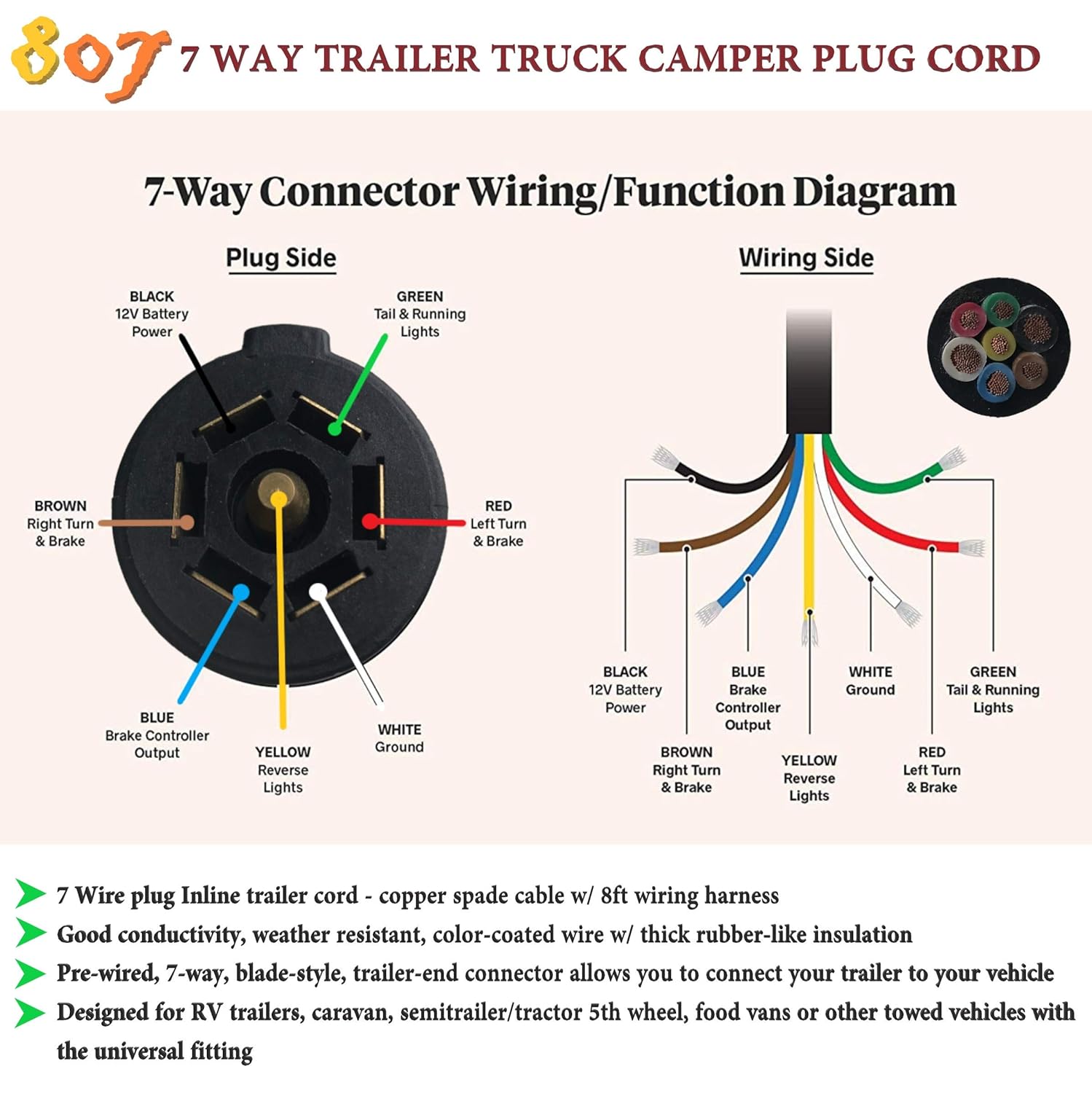
A 7 pin trailer wiring diagram is a schematic that shows the pinout and function of each wire in a 7-way round trailer connector. The standard 7-pin connector contains the following wires and functions: The diagram uses color coding and labeling to identify the purpose of each pin's wire. It traces the path of the wires from the connector.

7 point plug trailer wiring diagram
The colors for a 4-pin trailer wiring diagram are: White: Ground wire. Brown: Tail/running lights. Yellow: Left turn/brake light. Green: Right turn/brake light. 18-gauge wire is the minimum recommended size for the 4-way plug. This should be used for the lights.
Tips for Installing 4Pin Trailer Wiring AxleAddict
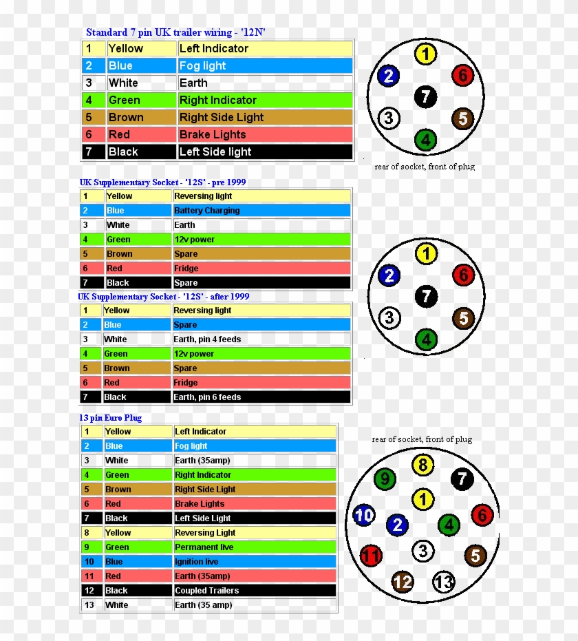
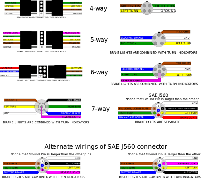
The images below show the Common Wiring Guide for Trailer Plugs, Adapters & Sockets. • Illustrations shown represent rear views of connectors. • The photos are what the adapters look like when removed from their housings. • The color key is a breakdown of the wires found in each of their respective systems. Note: The colors illustrated.
Four Pin Trailer Wiring Install Wiring Diagram & Info Mechanic Base
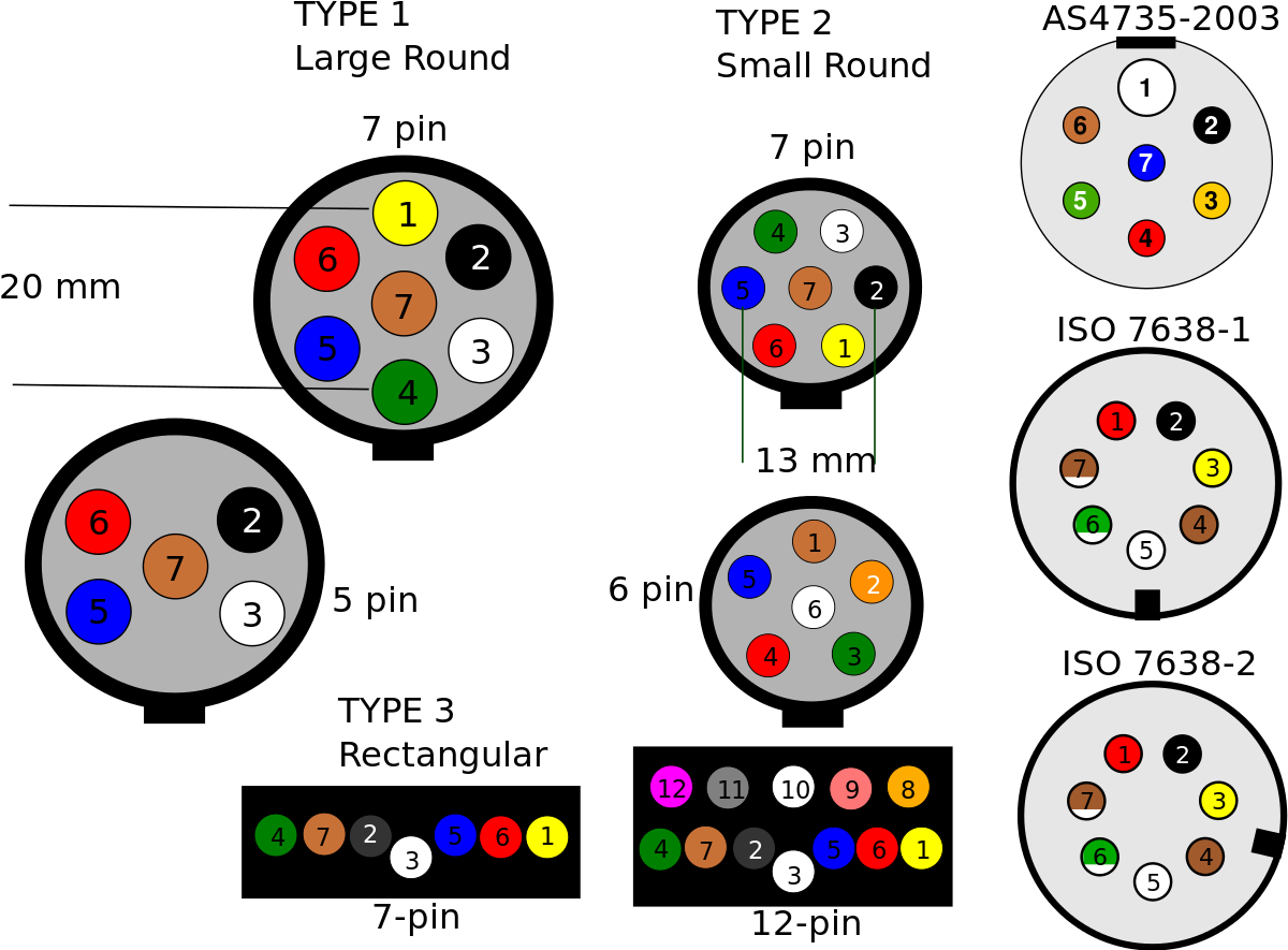
Four-way wiring connection. Five-way wiring connection. Six-way wiring connection. If you find that you have one of these non-standard connectors on your vehicle or trailer but also a 7 pin connector on the other end, you'll need to do one of two things: Use an adapter that can sync the two different types of connectors, which is the easiest.
7 Pin Trailer Plug Wiring Diagram Flat Wiring Diagram
5-Pin Trailer Wiring Diagram. In this 5-pin trailer wiring diagram above, you can see that the first wire is the ground wire (white). The second wire (green) to originate from the connector is responsible for the right signal. The third (brown) wire is the one that is responsible for the taillights. These are also connected to the side to.