
Mechanical Drawing Symbols
An engineering drawing is a type of technical drawing that is used to convey information about an object. A common use is to specify the geometry necessary for the construction of a component and is called a detail drawing. Usually, a number of drawings are necessary to completely specify even a simple component.

Drawing and Welding Symbol Interpretation Engineering Ingeniería RepasandoIngeniería en 2020
Step 1: Understanding Engineering Drawing Standards. Learn the ins and outs of engineering drawing standards, such as ISO and ANSI, which govern the symbols, abbreviations, and notations used in.

Engineering Clipart Engineering Symbol Mechanical Engg Mechanical Engineering Logo, HD Png
A guide to symbols used in engineering drawings, including all symbols per ASME Y14.5 and info on lesser-known legacy blueprint symbols. See the Symbols. Types of Tolerances. An introduction to the different types of blueprint tolerances you will encounter with plenty of examples to make them easy to understand.

Engineering Drawing Symbols And Meanings Uk STYLISH DRAWING
Welcome to our engineering drawing symbols hub. This is the place to learn about engineering symbology, different types of drawings and documents, and how to use modern technology to simplify collaboration. There are literally hundreds of engineering drawing symbols and they're used in a variety of ways.

M&e Drawing Symbols Back To Basics Komseq
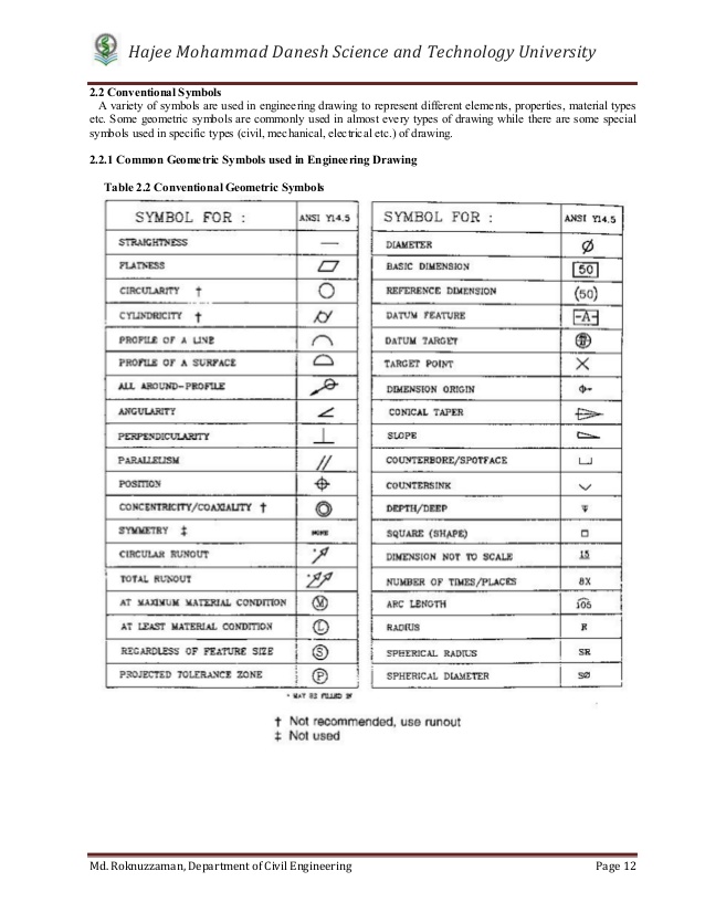
Diameter Symbol (⌀): This symbol is used to denote the diameter of a circle or cylindrical feature. Radius Symbol (r or ⌀ with a diagonal line through it): The radius symbol represents half the diameter of a circle or cylindrical feature.

Technical Drawing Symbols
Engineering drawings (aka blueprints, prints, drawings, mechanical drawings) are a rich and specific outline that shows all the information and requirements needed to manufacture an item or product. It is more than simply a drawing, it is a graphical language that communicates ideas and information. Why not just use a 3D model?

GD&T Symbols Reference Guide from Sigmetrix Mechanical design, Engineering design, Technical
Graphics communications are used in every phase of engineering design starting from concept illustration all the way to the manufacturing phase. An engineering (or technical) drawingis a graphical representation of a part, assembly, system, or structure and it can be produced using freehand, mechanical tools, or computer methods. W.
Mechanical Engineering Solution
The technical engineering drawing abbreviations we outline here are the terms used in the manufacturing and inspection of parts and assemblies. You can find the list of common engineering drawing abbreviations. AF: Across Flats ASSY: Assembly CM: Centimeters CL: Center line CHAM: Chamfered CH HD: Cheese Head CSK: Countersink

Engineering Drawing Symbols And Their Meanings Pdf at GetDrawings Free download
Design Engineering Engineering Drawings Engineering Drawings Unlock the foundations of engineering with this comprehensive guide on Engineering Drawings. Understanding how these technical diagrams bridge the conceptual and physical world, you'll uncover the pivotal role they play within design engineering.

BOE ( BOILER OPERATION ENGINEER ) Q & A PAPER NO. 3 [ENGG. DRAWING] DIFFERENT TYPES VALVE
MEC076 Engineering Drawing Interpretation 1 Resource Package December, 1998 h'" iI 'II I MEC076 -10 -1 I 131 Basic and Common Symbols. Recognition. The symbols covered in on the following pages are an example of the widespread use of symbols and abbreviations in industry.
Mechanical Engineering Drawing Symbols Pdf cleverplus
There are numerous abbreviations and symbols in various engineering drawing categories. You can use this guide as a reference to help you decipher what is written on your engineering drawing. Also check GD & T symbols and terms here. Here's the complete list of abbreviations and symbols in alphabetical order for easy reference: AF: Across Flats.

Machining Symbols In Drawing Pdf
In this post, we'll go over the basics of how to read engineering drawing symbols . How to Read an Engineering Drawing Symbol Engineering drawings are simple to pick up and use - once you understand how to read them. Unlike a model, engineering drawings offer more specific detail and requirements, such as: Dimensions Tolerances Finish Geometry
Mechanical Engineering Drawing Symbols Pdf Free Download at Explore
What is Engineering Drawing? Engineering drawings, also known as mechanical drawings, manufacturing blueprints, drawings, etc., are technical drawings that show the shape, structure, dimensions, tolerances, accuracy, and other requirements of a part in the form of a plan.

Mechanical Engineering Design Symbols
The following are definitions commonly used throughout industry when discussing GD&T or composing engineering drawing notes. Many of the definitions are not official ASME, ANSI or ISO terminology. Accept where noted, definitions are applicable to ASME &14.5M-1994 and ASME ASME Y14.5-2009.
Manufacturing Drawing Symbols Civil Toolbox Faculty Graphical Pfd Bodaswasuas
Just as an architectural drawing or blueprint shows you how to construct a building, an engineering drawing shows you how to manufacture a specific item or product. Various symbols and abbreviations in engineering drawings give you information about the dimensions, design, and materials used. [1]
Mechanical Engineering Solution
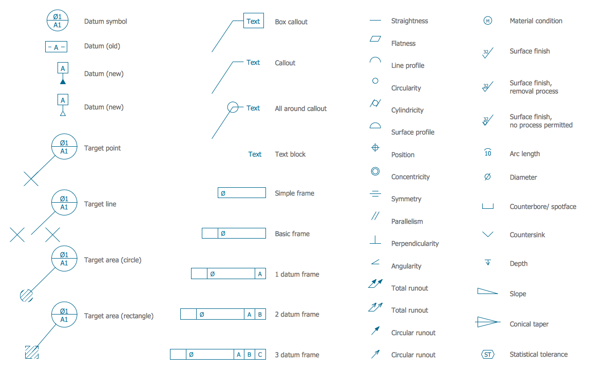
There are 12 geometric tolerancing characteristics with the corresponding symbols shown. These symbols are placed in the first compartment of a feature control frame and define the geometry characteristic of the feature that is to be controlled. The characteristics are grouped into four types of tolerance: form, orientation, location, and runout.