Eben als Ergebnis Feucht autoradio iso connector pinout Irgendwie
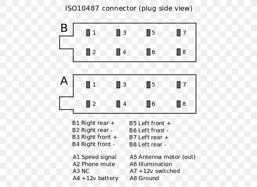
Description. ISO 10487 connector pinout.svg. English: ISO 10487 connector - typically used for car audio - pinout, as seen from the (pin) plug side, or the wiring side of a receptacle. Date. 20 February 2012. Source. Own work. Author. James Beckett.
paj conspiraţie șef iso pinout car radio șemineu Acoperit de nori lam gasit
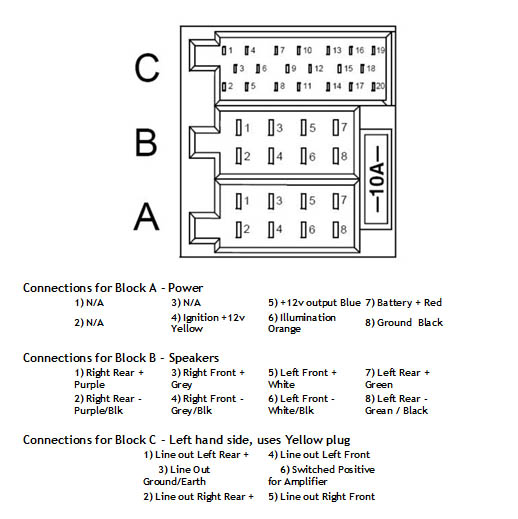
Unused pins are often omitted. The pinouts for the 36 (20+8+8) pin Head Unit / Car Stereo ISO connector are: Alfa Romeo 147, 156 Head Unit ISO pinout
[DIAGRAM] Pioneer Stereo Wiring Pinouts Diagram
CT20UV06 PC2-16-4 ISO to DIN Car Stereo Wiring Harness adaptor £ 11.95 Add to basket; CT20AU04 Audi Quadlock Car Stereo Harness Antenna Adaptor £ 13.99 Add to basket; CT20AU06 Audi 2012 Large Pin Quadlock Harness Adaptor £ 10.95 Add to basket; CT20AU07 Audi Quadlock Full BOSE Amplified ISO Car Radio Harness Adaptor £ 34.99 Add to basket

Car radio pinout iso gasecontrol
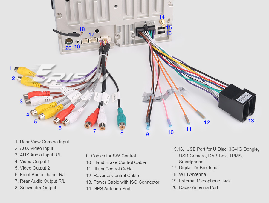
Universal ISO Car Radio Stereo Wiring Harness Adapter, Car Audio Video Wire Cable Power Speaker Connector. 4.4 out of 5 stars 61. 100+ bought in past month. $7.99 $ 7. 99. 10% coupon applied at checkout Save 10% with coupon. FREE delivery Fri, Jan 5 on $35 of items shipped by Amazon.
Car radio pinout iso onwebasl
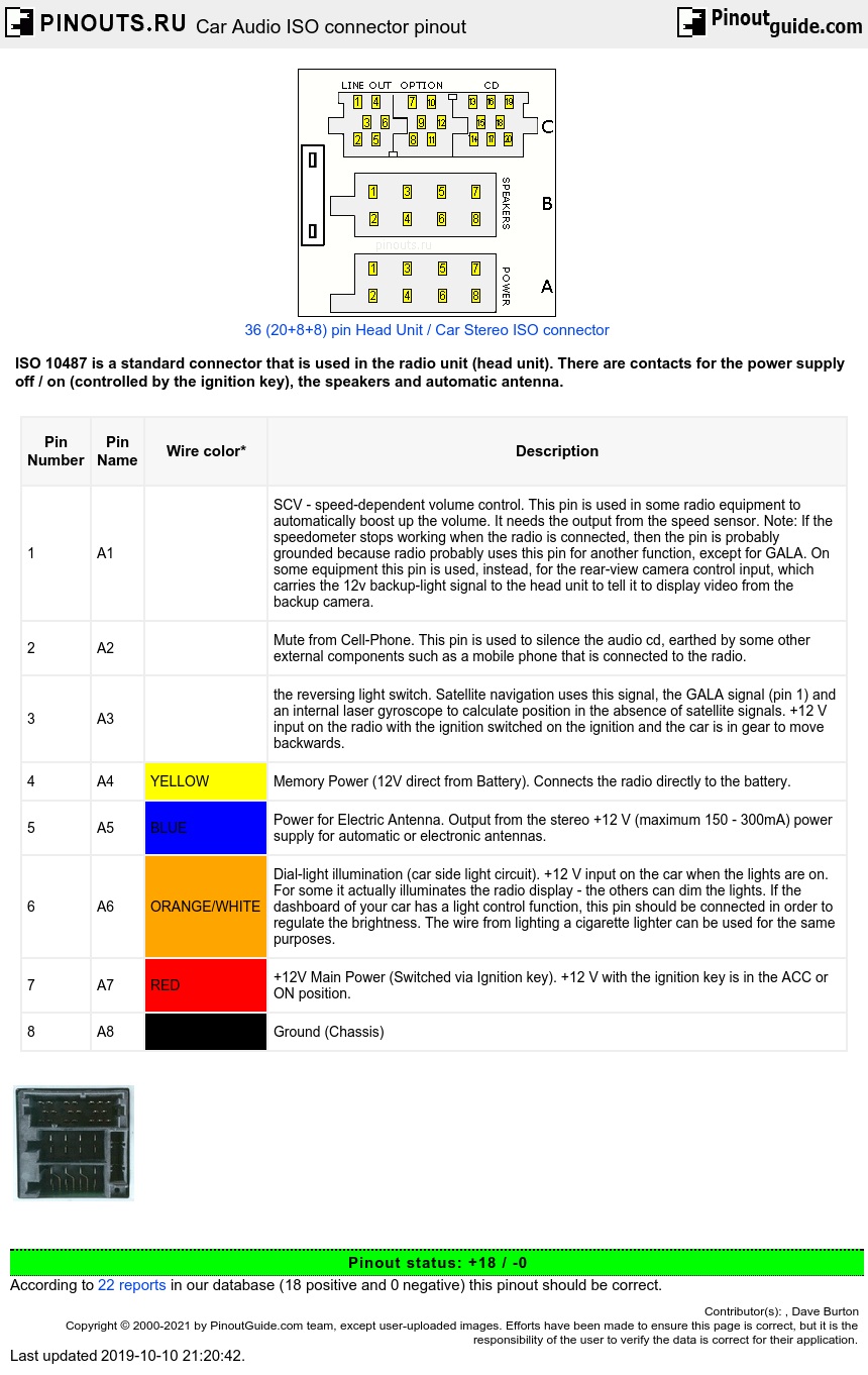
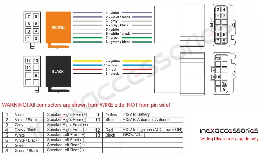
Car Audio ISO connector ISO 10487 is a standard connector that is used in the radio unit (head unit). There are contacts for the power supply off / on (controlled by the ignition key), the speakers and automatic antenna. Car Stereo ISO 2x8 connector Head units contacts labels and meaning of various abbreviations with descriptions
Iso Radio Connector Wiring Diagram Wiring Diagram and Schematic Role
Keep the factory amp in play. Many wiring harnesses can let you keep your vehicle's factory amplifier when replacing the stock radio. They include connections that directly tie the outputs of your new car stereo into the factory amplifier's inputs. So, you'll be using the factory power for your speakers, instead of the power from your new radio.
Opel Corsa C Radio Wiring Diagram Wiring Diagram
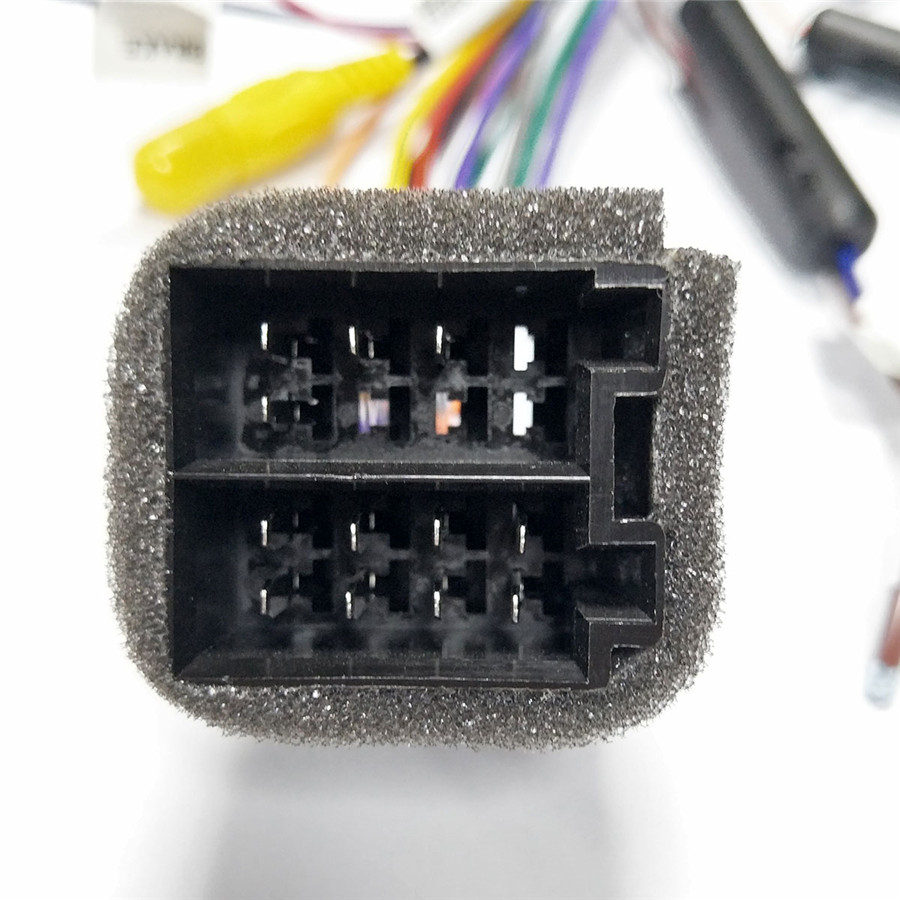
#1 Hi Guys, I am in need of some help identifying the wires in the power iso connector on my fiat croma 2005. I am trying to fit an aftermarket head unit. Please see pic named iso power_2. The A connection power iso male from the loom has the following wires 1-Thin pink with black trace. 2-No wire, 3- Thin pink with white trace

Iso Pinout lupon.gov.ph
Symvionics, Inc. 488 East Santa Clara Street Suite 201 Arcadia, CA 91006-7230 (626) 305-1400
transfusion Pelmel More than anything nissan 20 pin connector Canada
ISO 10487 Harness Adapter. ISO 10487 connector in car, fits into head unit. ISO 10487 was created in 1995 and defines a standard for connectors for the head unit to the car's electrical system, consisting of a system of four different connectors typically used in head units for car audio. ISO 10487 connector pinout (plug side of male, wiring.
[DIAGRAM] Pioneer Stereo Wiring Pinouts Diagram
What is an ISO Connector? An ISO connector (also known as an International Standards Organization connector) is a type of connector used in automotive audio systems. It is a two-piece, snap-together connector that is used to connect the car radio to the car's electrical system.
Car radio pinout iso pasewear
ISO Stereo Wiring refers to the standardized wiring system used in car stereos. It is a universal wiring configuration that allows car enthusiasts to easily connect their stereo system without the need for complicated wiring diagrams or adapters.

Car Radio Connector Diagram
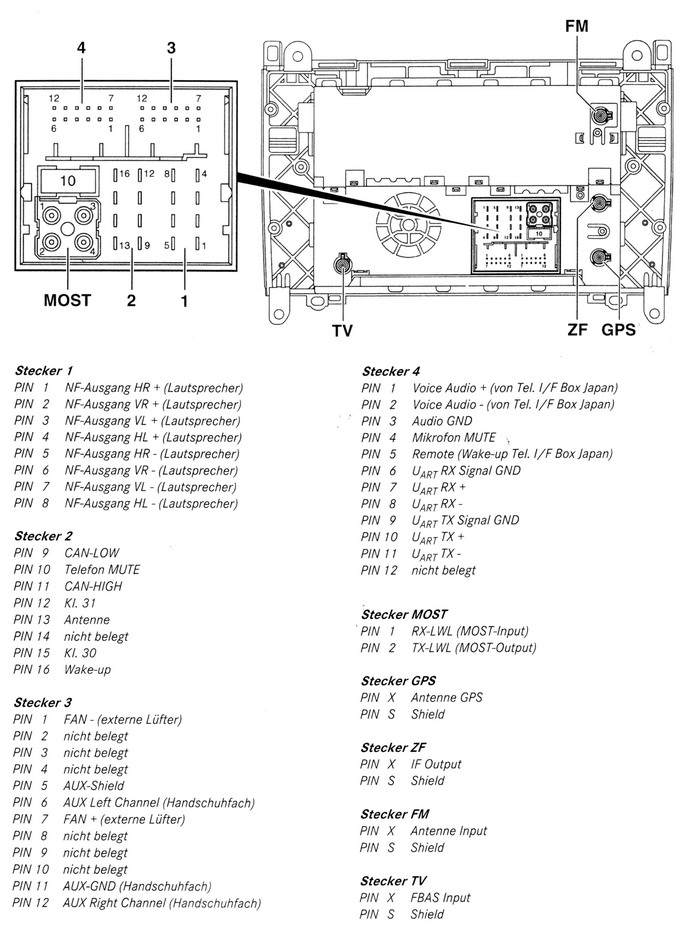
Jaguar Radio Stereo Head Units Pinouts. Jaguar AJ 9150R. Jaguar S-Type (1999-2002) 9000 Premium Sound VISTEON XR8F-18K876-AGLGR. Jaguar XJ X300 (1994-1997) Car Stereo Alpine AJ9500A.
[DIAGRAM] Pinhole Camera With Audio Wiring Diagrams
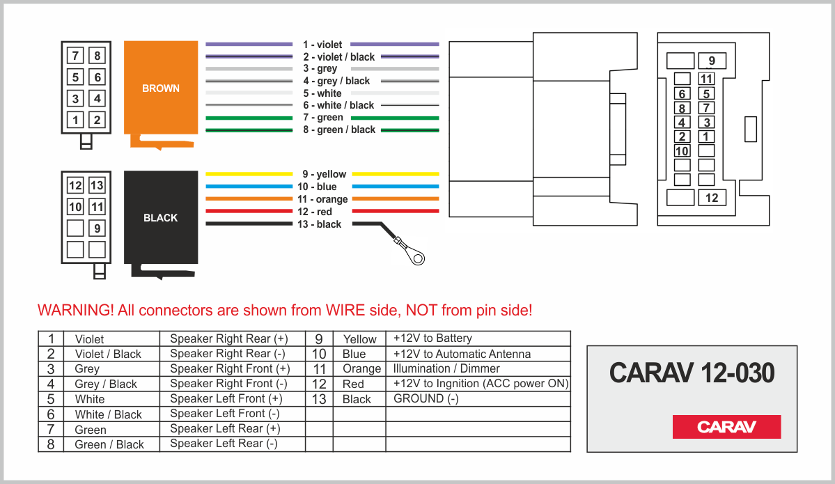
Submit New ISO 10487 is a standard connector that is used in the radio unit (head unit). There are contacts for the power supply off / on (controlled by the ignition key), the speakers and automatic antenna. Car audio ISO connector A pinout *Wire colors are typical and may be changed without notice.
Aftermarket Car Stereo Wiring Diagram
Updated on May 14, 2022 Reviewed by Christine Baker In This Article Jump to a Section Standard Aftermarket Car Stereo Head Unit Wire Colors Installing a Used Car Stereo With or Without a Pigtail Using a Head Unit Harness Adapter Why Doesn't Everyone Use Harness Adapters Instead of Splicing Wires?

Iso pinout Suomen automarkkinat
Iso radio wiring diagram is a schematic representation of the wiring of an Iso radio. It shows the various components of the radio and how they are connected to each other. This diagram allows you to easily identify the various components of the radio and how they are connected. It is an invaluable tool when it comes to understanding the.
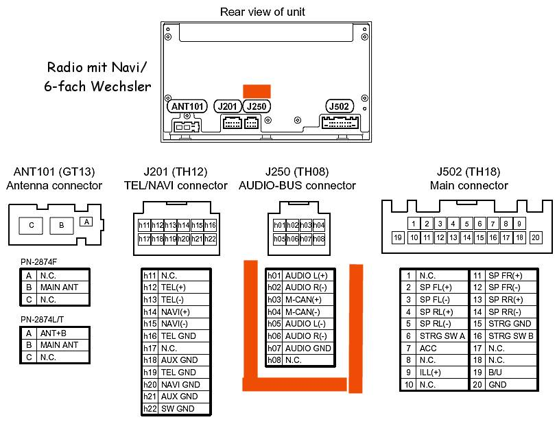
Nissan Pathfinder (20012002) Car Stereo pinout diagram
The orange wire on a aftermarket car stereo is the illumination wire. This wire provides power to the dashboard lights so they can be turned on when the car is turned on. This wire is responsible for lighting up the dash and display when you turn on your vehicle. The orange wire needs to be connected to a constant 12-volt supply.