ELEKTRONIKA DAN MIKROKONTROLER Membuat PWM (Pulse Width Modulation
Rangkaian timer IC 555 terutama digunakan pada aplikasi multivibrator astabil, multivibrator monostabil, konverter DC-DC, generator bentuk gelombang, probe logika digital, takometer, pengukur frekuensi analog, perangkat pengukur suhu, perangkat kontrol, dan pengatur tegangan.
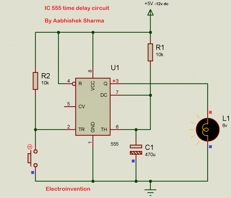
IC 555 Delay Timer circuit Easy timer circuit on off delay circuit
The output of this IC 555 is a pulse width modulated wave. This PWM signal is applied as the trigger input to the second IC 555 which is operating in monostable mode. The position of the output pulses of the second IC 555 changes according to the PWM signal, which is again dependent on the modulating signal. The schematic of the Pulse Position.
Hobby Electronics Circuits Proteus 555 Timer illustration to turn On
The figure above shows how a servo motor can be operated precisely using PWM signals from the IC 555. The rate of pulses repeated by the circuit can be anything between 20 Hz and 70 Hz. We can vary the positive pulse width from 1 millisecond to 2 milliseconds (ms). When the PWM is set at 1 ms the servo rotates to one of its extreme positions.

Simulasi Rangkaian PWM Analog IC NE 555 for DC Motor Using Proteus
IC 555 adalah rangkaian waktu monolitik yang menghasilkan penundaan waktu atau osilasi yang akurat dan sangat stabil. Jika dibandingkan dengan aplikasi op-amp di area yang sama, IC 555 juga sama-sama andal dan murah dalam hal biaya.
Circuit Diagram Of Pwm Using 555
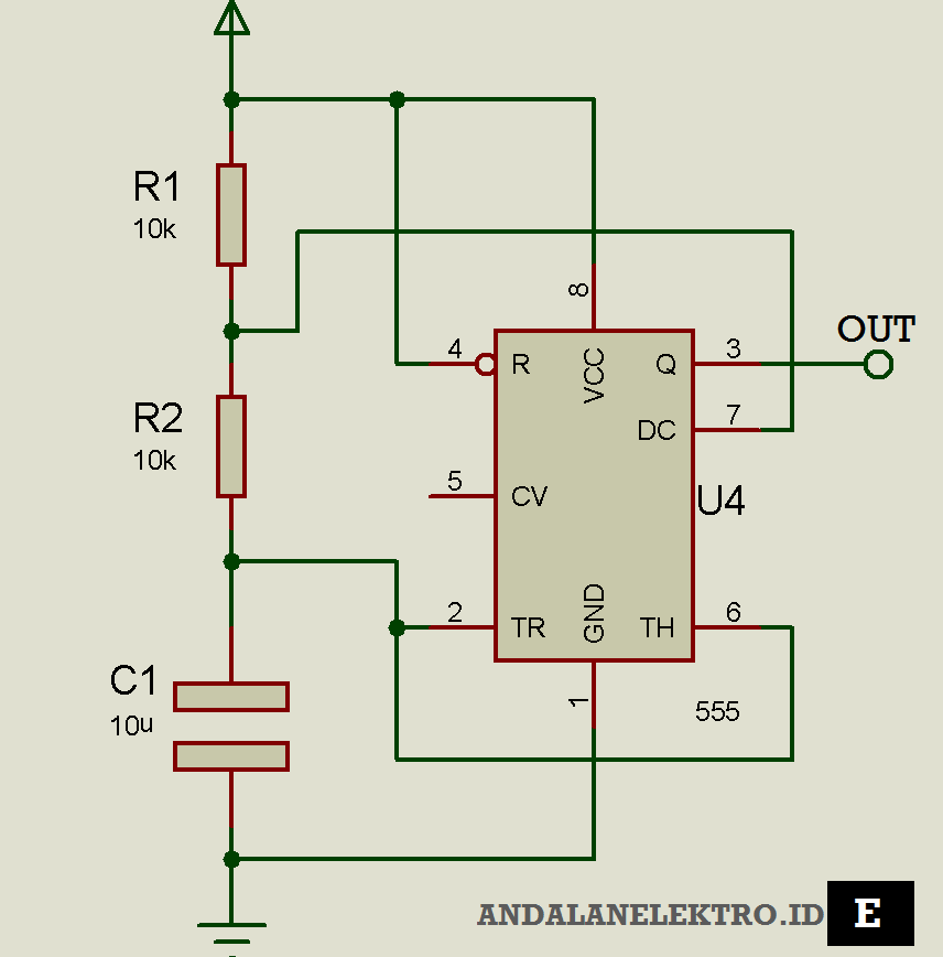
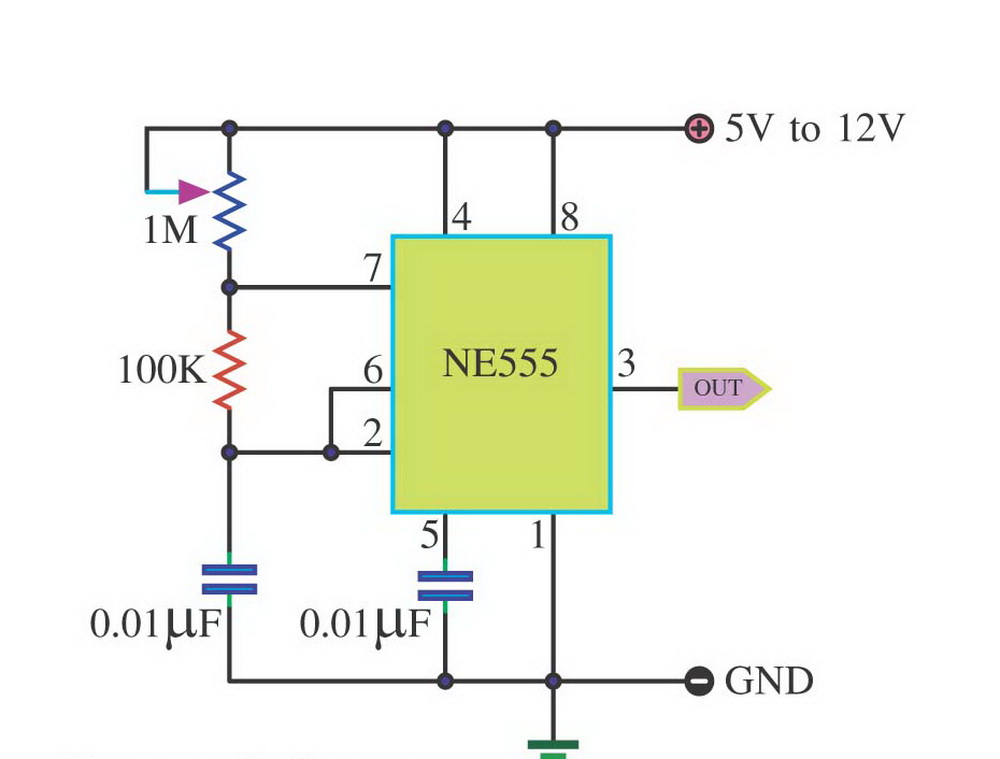
Rangkaian ini dapat dimanfaatkan sebagai penunda waktu, pendeteksi pulsa gelombang yang hilang, bouncefree switch / penekanan switch sekali dan latch, saklar sentuh, pulse wide moulation (PWM), pembagi frekuensi, dan kapasitansi meter. Berikut gambar rangkaian simulasi rangkaian monostable :
Pwm Circuit Diagram Using 555
What's PWM PWM stands for pulse width modulation, a process which involves the control of the pulse widths, or the ON/OFF periods or logical outputs that's generated from a particular source such as an oscillator circuit or microcontroller.

Generate Pulse Width Modulation (PWM) Signal using 555 Timer IC
Find the deal you deserve on eBay. Discover discounts from sellers across the globe. Try the eBay way-getting what you want doesn't have to be a splurge. Browse 555 pwm controller!
Circuit Diagram Of Pwm Using 555
It has a voltage divider circuit with three 5K Ohm resistors in series. 556 is a dual timer IC. The internal block diagram of 555 is as follows. Internal Block diagram of 555-Timer.. Constant frequency PWM Using 555-Timer. With the basic astable circuit, the duty ratio cannot be controlled without affecting the frequency. Using.
Ic 555 Timer Circuit Diagram
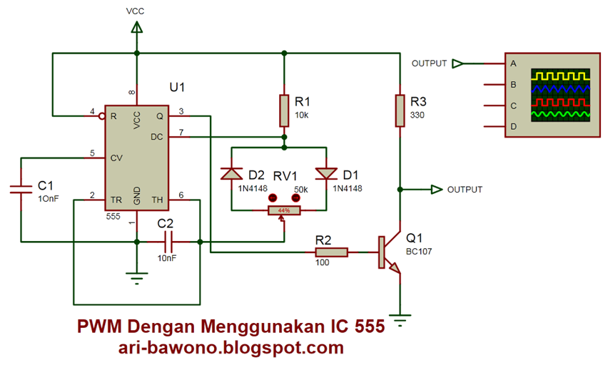
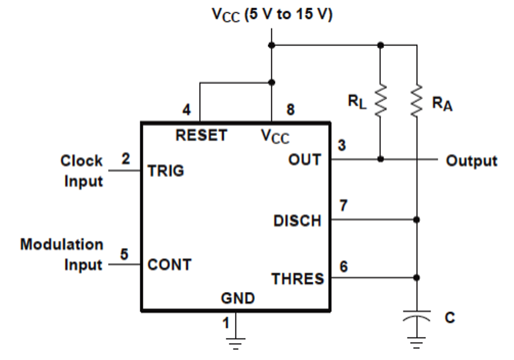
The control pin of the 555 Timer is not used but it's connected to a 100nF capacitor in order to eliminate any external noise from that terminal. The reset, pin number 4, is active low so therefore it is connected to VCC in order to prevent any unwanted reset of the output. The output of the 555 timer can sink or source a current of 200mA to.

Membuktikan inverter dengan PWM IC 555 output driver ke trafo memakai
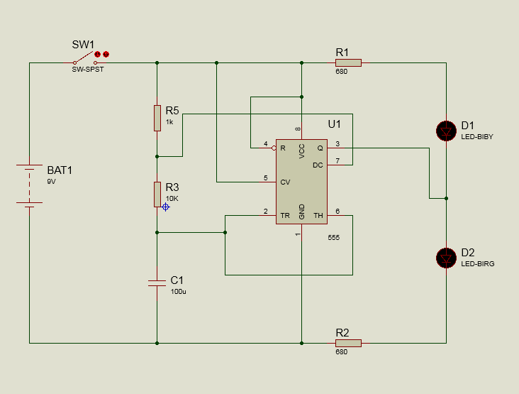
Rangkaian yang paling sering dibuat mengunakan IC Ne 555 ini adalah Lampu LED Flip - flop dimana lampu akan bergantian (mati dan nyala) secara terus menerus. Kecepatan nyala dan mati lampu bergantung dari seberapa cepat Clock Speed - nya dan dapat diatur menggunakan rumus yaitu : Td = 1,1 RC Keterangan : Td : Time Delay (Sekon) R : Resistor (Ohm)
Prinsip Kerja Rangkaian IC 555, Rumus Frekuensi dan Duty Cyclenya
In this way, PWM signals are generated at the reference pin of the motor. Now in this case on the time period of generated pulse is greater than 1.5 milliseconds, which you can calculate by the duty cycle formula for 555. And thus we get 90-degree clockwise rotation of the motor as explained in the above paragraph. 2.

Generate Pulse Width Modulation (PWM) Signal using 555 Timer IC
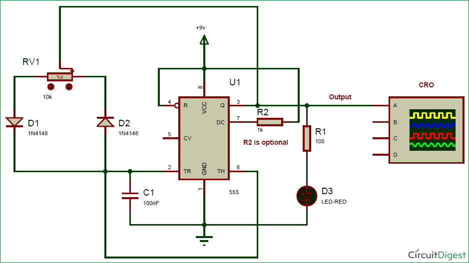
Kami akan menjelaskan apa itu rangkaian PWM, menguraikan fungsi utamanya, memberikan panduan langkah-langkah untuk menyusun rangkaian dengan IC 555, dan menyajikan prinsip kerja yang mendasarinya. Dengan membaca artikel ini, pembaca akan mendapatkan wawasan mendalam tentang cara merancang dan mengimplementasikan rangkaian PWM IC 555 dengan profesional.
pwm circuit diagram using 555 IOT Wiring Diagram
Duty Cycle = (THIGH / T) * 100. Frequency of the PWM Signal describes the rate at which the signal completes one cycle. The above image shows different PWM Signals and different Duty Cycles along with the output voltage. It is vey easy to generate a PWM Signal using 555 Timer IC. But before seeing how 555 Timer PWM signal is generated, you need.
Skema Lampu Strobo Ic 555 Ruang Ilmu
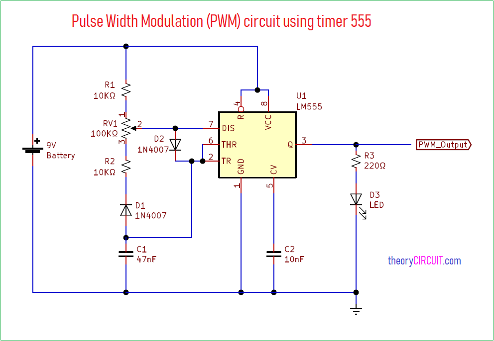
"The 555 Timer is an 8 pin Integrated Circuit that generates accurate timing pulse. The designing of the 555 timer is done by collectively arranging the electrical and electronic components such as resistors, transistors, diodes and Flip Flops.". Implementation of PWM using 555 Timer in Proteus ISIS

Share IC 555 Pengatur Kecepatan Motor DC Sederhana
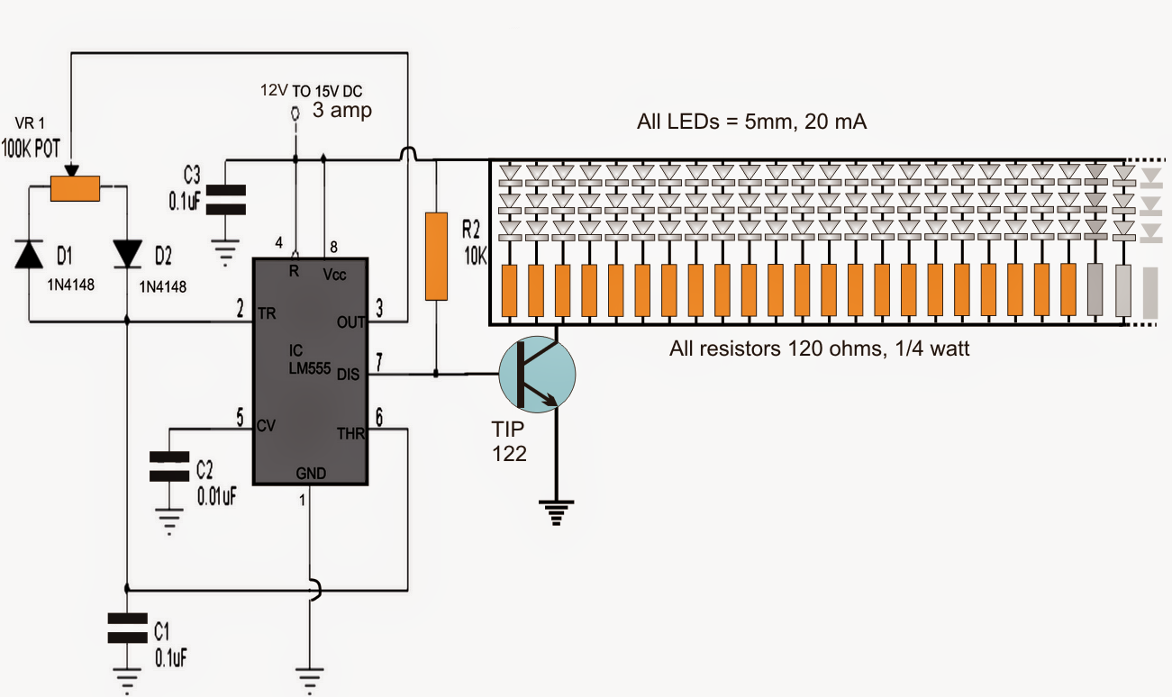
PWM dc motor speed controller Circuit Diagram. Place a 555 timer IC in the middle of the breadboard. Then connect the power supply to the positive and negative rails of the breadboard. Attach pin 1 of the IC to the negative rail and pin 8 to the positive rail of the breadboard. Place the tip-122 MOSFET and join its emitter pin to the positive.

Prinsip Kerja Rangkaian IC 555, Rumus Frekuensi dan Duty Cyclenya
In this project, we are making a "Servo Motor Controller using 555 Timer IC". A servo motor is an "actuator" that is used to control the angular position, velocity, and acceleration. Servo motor operates at the "PWM" principles, which implies its angle of rotation is constrained by the span of the pulse applied to its "Control PIN".