9 LED Patterns with Arduino Arduino Project Hub
Display. Library to easily control LED Strips. Simple Arduino library with ready-to-use customable animations for addressable LED Strips. Author: Dono7. Maintainer: Dono7. Read the documentation. Compatibility. This library is compatible with all architectures so you should be able to use it on all the Arduino boards. Releases

16x32 LED Matrix Display Module with Arduino YouTube
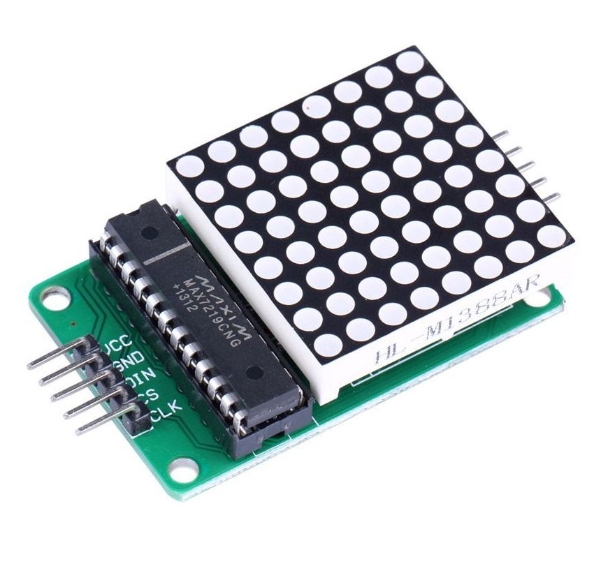
The Arduino will connect to the MAX7219 and send commands to it with the SPI communication protocol. Based on commands from the Arduino, the MAX7219 will output high or low signals to turn each LED on and off: How LED Matrixes Work

4Digit 7Segment LED Display + Arduino 3 Steps Instructables
MAX7219 LED dot matrix display specifications How to connect the dot matrix display to the Arduino Hardware SPI pin locations MAX7219 LED dot matrix display connections Power requirements Installing the MD_Parola and MD_MAX72XX Arduino libraries Different types of LED dot matrix displays FC-16 8×8 or 8×32 module Module orientation and connections

Control a 4 Digit 8Segment LED Display Arduino YouTube
Step 4: Solder LED Display & Resistors. Place LED display pins from backside of PCB aligning the pins 1-A5, 6-A0 & 12-D4, 7-D9. Solder the 12 LED display pins to the Arduino Nano. Place 4 SMD resistors between the Pad and the tinned trace from Step 3.

Arduino powered 300 RGB LED display. An brief "How to". YouTube
Programming 4 Digit 7 Segment LED Display. Getting started by. SAnwandter1.. Arduino DIY LED Control with LDR Sensor (Photoresistor) Getting started by. agarwalkrishna3009.
Using a 7 Segment LED Display w/ Arduino Uno rastating.github.io
Display consists of a few LED Modules, but form API perspective they are connected together into one continuous canvas. You can place on this canvas bitmap on any position given by standard x,y coordinates. The paint method has following syntax: paint (pixel_t x, pixel_t y, pixel_t width, pixel_t height, uint8_t data).
Arduino LED Display 12 Steps Instructables
Step 2: Wiring the Display and Button. Now, to wiring! To make it easier for you, I am going to put the Arduino pin number first, then the display's pin number. If this is too confusing, say so in the comments, and I'll rewrite it. Connect the button to Arduino pin 13 and 5V.

Arduino LED 8X8 Matrix Display MAX7219
LED includes two pins: Cathode (-) pin: needs to be connected to GND (0V) Anode (+) pin: is used to control LED's state How It Works After connecting the cathode (-) to GND: If connecting GND to the anode (+), LED is OFF. If connecting VCC to the anode (+), LED is ON.

1. Introduction This demonstration show you how to connect a LED Matrix module to Arduino ESP32
The process of controlling the display involves putting the data that form the image of what you want to display into the data registers, then putting instructions in the instruction register. The LiquidCrystal Library simplifies this for you so you don't need to know the low-level instructions.

Programming 4 Digit 7 Segment LED Display Arduino Project Hub
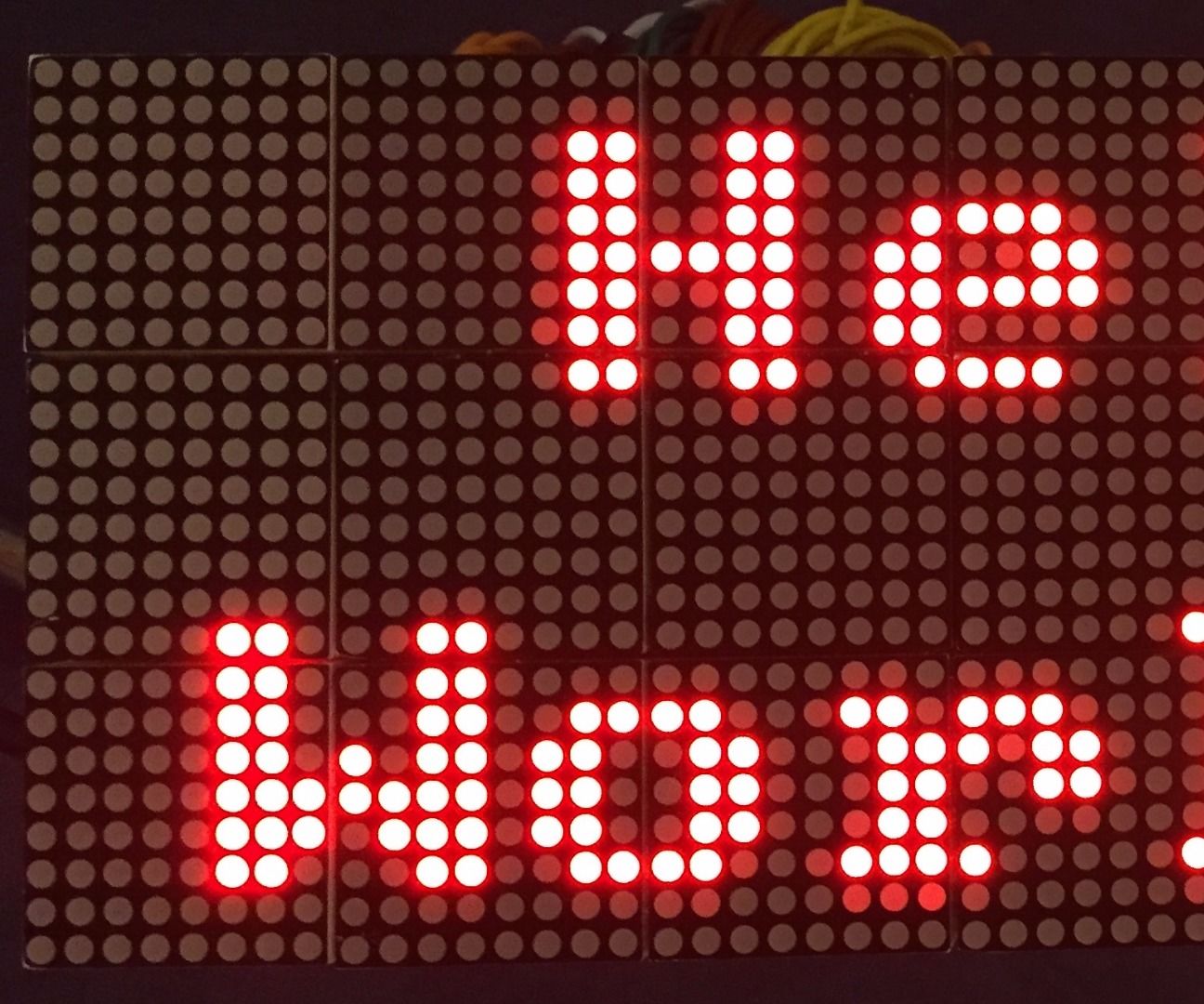
An Arduino display can serve a variety of purposes. Since micro controllers usually read data from sensors, a display allows you to see this information in real-time without needing to use the serial monitor within the Arduino IDE.. Cell phones, televisions, and other modern display applications use Dot matrices. LED matrices are available.
Serial 7 Segment Display Arduino Uln2803apg newlineparent
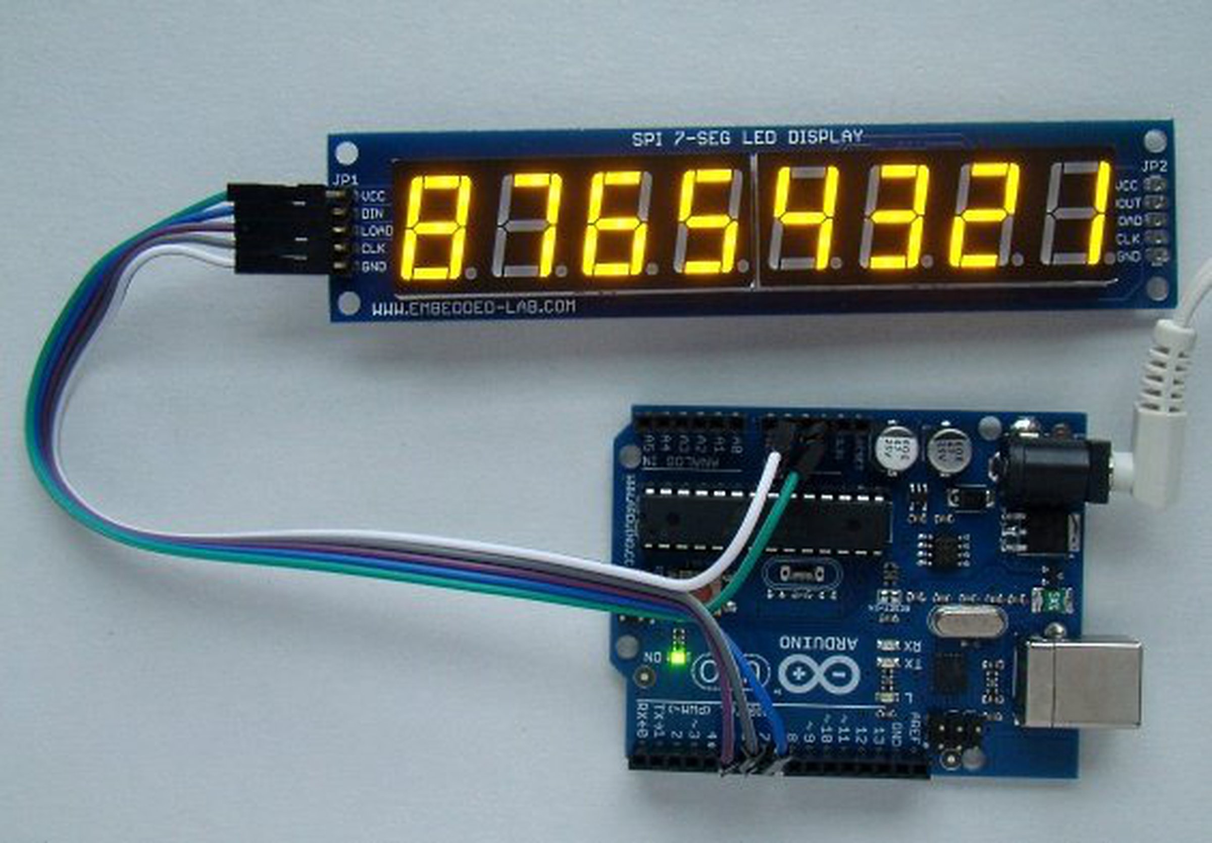
Display Print text to an Avago HCMS-29xx LED display. The HCMS 29xx displays are pretty little displays that contain a row of 5x7 LED matrices. You'll need five digital output lines to control them. LedDisplay manages all the necessary pin control and data shifting for you. Author: Tom Igoe Maintainer: Paul Stoffregen Read the documentation
 1.jpg.2560x2560_q85.jpg)
7Segments LED Display Arduino Kit from alicemirror on Tindie
The figure below shows a 16×2 LCD front and the back view. This LCD has 2 rows, and each row can display 16 characters. It also has LED backlight to adjust the contrast between the characters and the background. When you buy a 16×2 LCD, usually it doesn't come with breadboard friendly pins. So, you may need some headers.
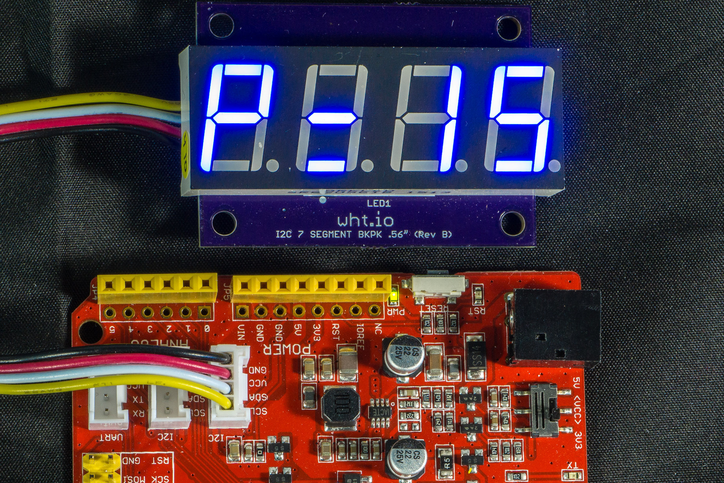
GitHub Arduino library for controlling I2C 7
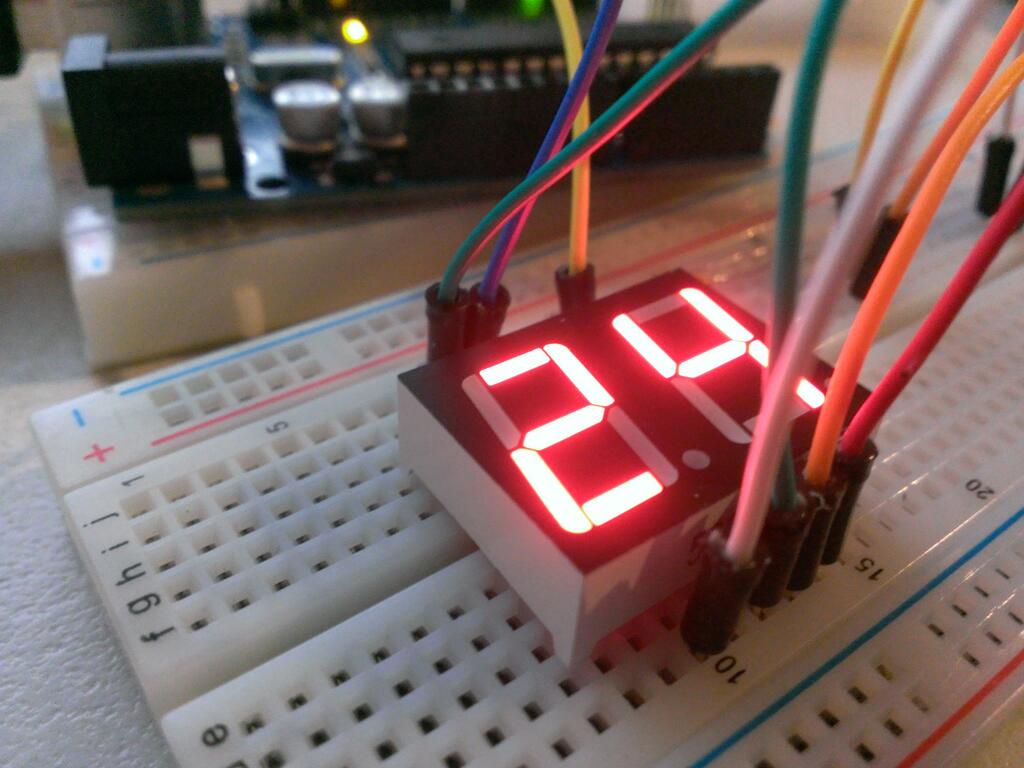
They're a simple and effective way to display numerical information like sensor readings, time, or quantities. In this tutorial, we'll see how to set up and program single digit and multi-digit seven segment displays on an Arduino. Seven segment displays come in a wide variety of sizes and colors.

Arduino 7 Segment LED Display Tutorial (TM1637 4 Digit)
Use both 7-segment and dot-matrix LED displays with an Arduino.Article with code: https://dronebotworkshop.com/led-displays/More articles and tutorials: http.
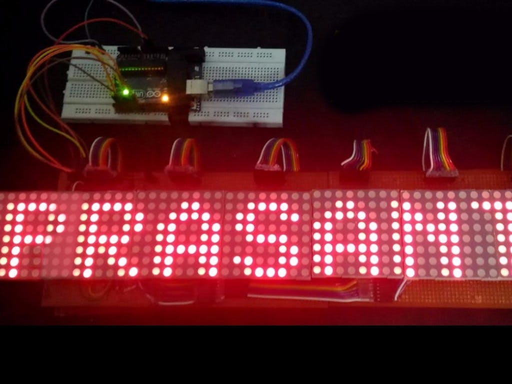
48 x 8 Scrolling LED Matrix using Arduino. Hackster.io
The organic light-emitting diode (OLED) display that we'll use in this tutorial is the SSD1306 model: a monocolor, .96-inch display with 128×64 pixels as shown in the following figure. The OLED display doesn't require backlight, which results in a very nice contrast in dark environments.
Arduino LED Matrix display 8x8 dots (MAX7219)
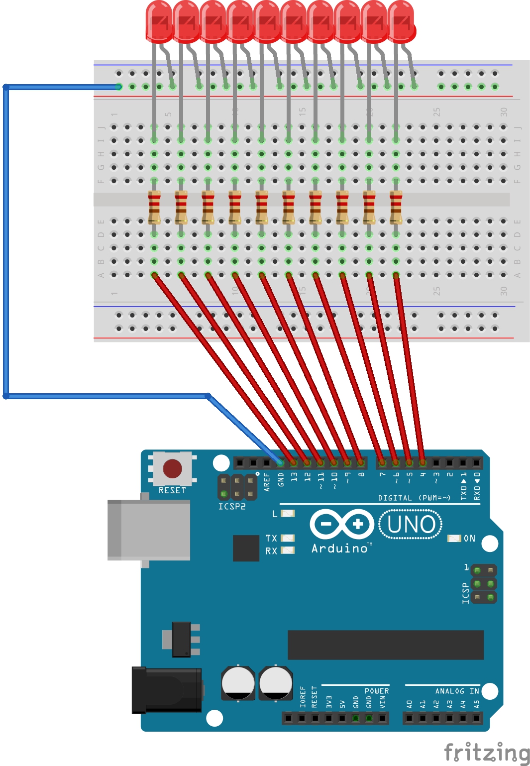
LED (any color, I will use red). Breadboard. 220 Ohm resistor (more info on the value later on). Some male to female wires. Build the circuit Here is the circuit. How to build the circuit: First make sure that the Arduino is powered off (no USB cable plugged to anything).