
GTU MECHANICAL DRAFTING 2 nd SEM DIPLOMA IN MECHANICAL MACHINING SYMBOL
Beginner's Guide to GD&T Symbols Check out our complete guide to GD&T symbols with tips to help you read and understand your manufacturing blueprints. Learn About GD&T Symbols Ready for more? Explore blueprint reading topics Datums Many dimensions on a blueprint are based on datums. Find out how to use them and where they fit into your measurement.

GD&T Symbols Reference Guide from Sigmetrix Mechanical design
Maximum Material Condition (MMC), is a feature of size symbol that describes the condition of a feature or part where the maximum amount of material (volume/size) exists within its dimensional tolerance. Learn Symbol → Flatness GD&T Flatness is a common symbol that references how flat a surface is regardless of any other datum's or features.

How To Read Machining Drawing Lori Sheffield's Reading Worksheets
Surface Roughness Chart Symbols and Abbreviations. When you search for machining surface finish symbols on your favorite browser, you would notice a range of abbreviations. These include Ra, Rsk, Rq, Rku, Rz, and more. They are units used in measuring surface finish. Ra - Average Surface Roughness

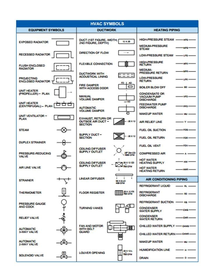
Blueprint Symbolsblueprint Symbols Hvac Design
During the design process, surface roughness symbols indicate what is required and efficiencies can be made during the machining process. That said, irregular textures can still be created as a result of the die or cutting tool instability. Roughness impacts performance of a mechanical component, so precision finishing is crucial.

Machining Symbol Roughness Symbol Grade Number Roughness value
Surface finish symbols are needed to represent the surface texture requirement to manufacturers. If you are working on CNC machining parts or some other manufacturing process. then you need to specify the surface finish requirement to manufacture. You can use surface finish symbols to tell the manufacturer about your surface finish requirements.
surface finish symbols in engineering drawing
Symbols For Features Radii Half of a circle. The distance from the center of a circle to the edge. Diameters The distance all the way across a circle. Two times the radius. This symbol gets used with other symbols as well such as counterbores, countersinks, and true position callouts. Depth of This symbol specifies the depth of a feature.
Surface Finish Symbols
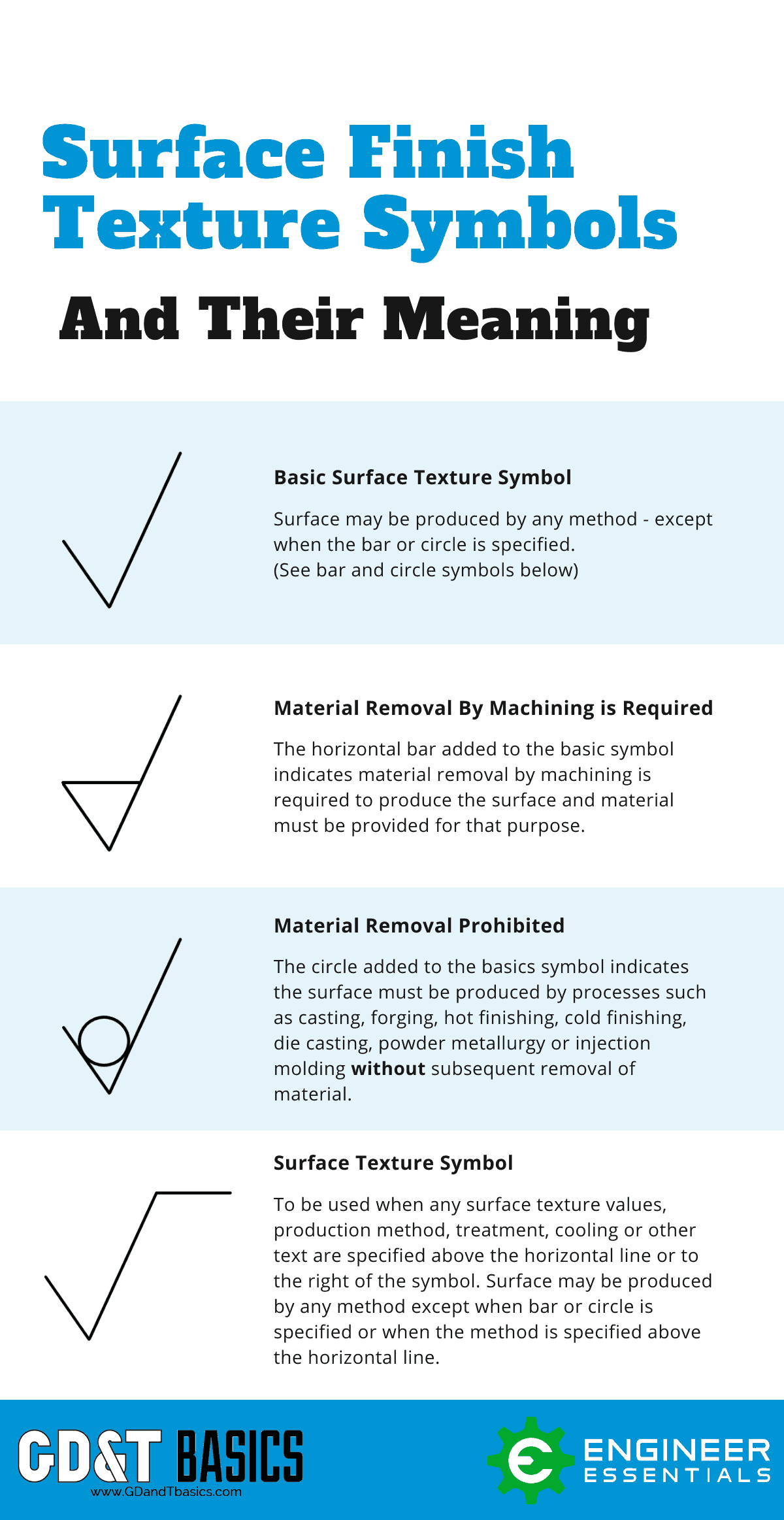
2. This symbol has a bar added to the basic symbol, and forms a triangle. it indicates a surface that requires a material removal process and allowance indicated. Surface texture obtained by the removal of material by machining operations like turning, drilling, milling, etc.
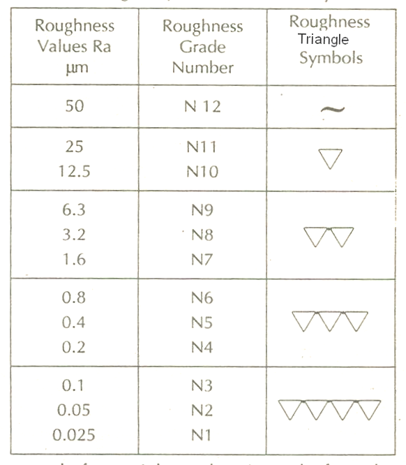
Image Gallery Machining Symbols
Material removal by machining is required symbol This symbol indicates that material removal by machining is necessary for the desired surface finish to be achieved. A horizontal black bar is added to the basic surface texture symbol to indicate this. Material removal prohibited symbol
Cnc machining icon Royalty Free Vector Image VectorStock
a: Passband or sampling length and surface texture parameter symbol and value b: Indications of the second and subsequent parameters when multiple parameters are required c: Machining method d: Crease and its direction e: Machining allowance The descriptors shown below are used when pictorially representing surface roughness.

machining drawing symbols chart Lamer
These standards define the symbols, rules and best practices for using and interpreting GD&T. The latest edition is ASME's Y14.5 - 2018. According to the ASME, the five categories of GD&T symbols are: Form controls. Profile controls. Orientation controls. Location controls.
machining surface finish symbols triangle Aron Ness
Surface finish is composed of three distinct elements - roughness, lay, and waviness (See Figure 1 below). However, it is not uncommon in machine shops for the term surface finish to be used to describe only surface roughness. Roughness is the most commonly specified aspect of surface finish, however, before we get into the details Surface.

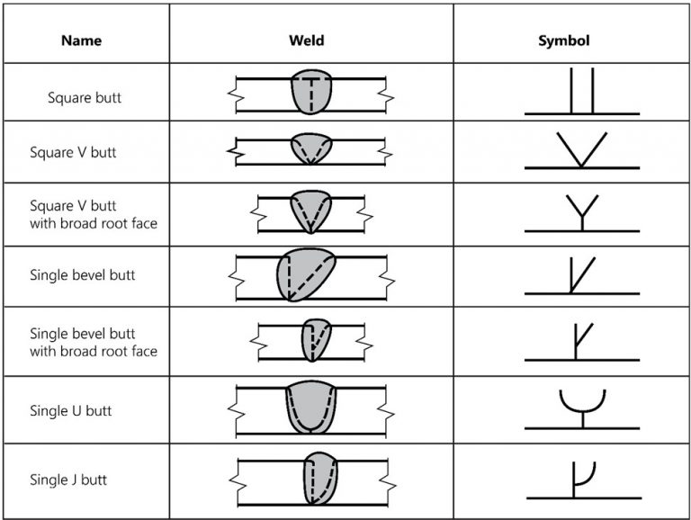
Basic Weld Symbols
May 1, 2022 by Brandon Fowler Geometric dimensioning and tolerancing (GD&T) consists of a set of symbols and rules for applying them that communicates the requirements of an engineering blueprint. GD&T controls variations of size, form, orientation, location and runout individually or in combination.

16+ Machining Blueprint Symbols, Great!
The symbols define the situation of the creases made by the edged tool during machining to the surface captured in the diagram in which the symbol is written. The arrow represents the direction of the movement. The symbol of a circle is the point of application of the initial load on the surface (an edge tool, for example).
CNC machine tool vector icon 2204708 Vector Art at Vecteezy
A good design drawing can indicate all the details needed to produce a mechanical CNC milling part in an easy way. Because there is no large space on a drawing to contain all the text to illustrate the image, abbreviations, and symbols are often used in engineering drawings to communicate the characteristics of the product to be manufactured.
16+ Machining Blueprint Symbols, Great!
Among the most crucial machine surface finish symbols and abbreviations to know include: Ra - (Average Surface Roughness)

Mechanical Engineering Symbols Cadbull
A 45 degree lead angle facemill will produce a finer finish. - Use inserts with a larger radius. A toroidal cutter or copy mill can often leave a better finish than other insert geometries. - Unless the insert height on your face mill can be individually adjusted, a fly cutter often leaves the best surface finish.