How to Assemble Drum Brakes (A StepbyStep Guide) OnAllCylinders
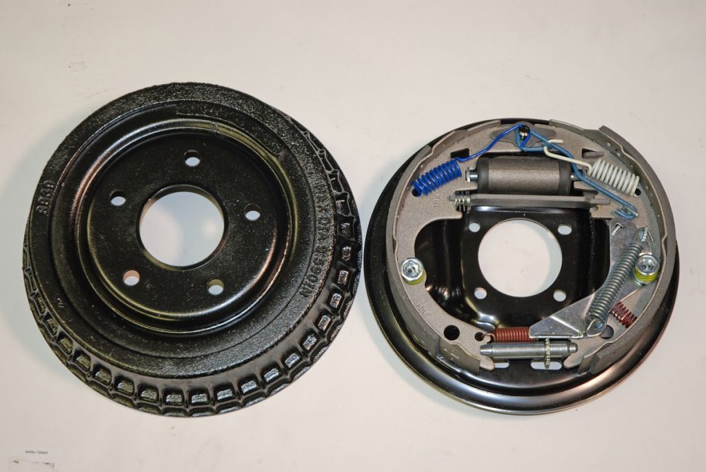
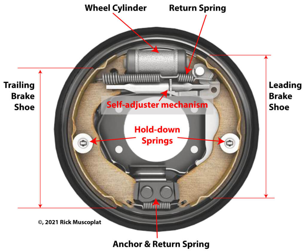
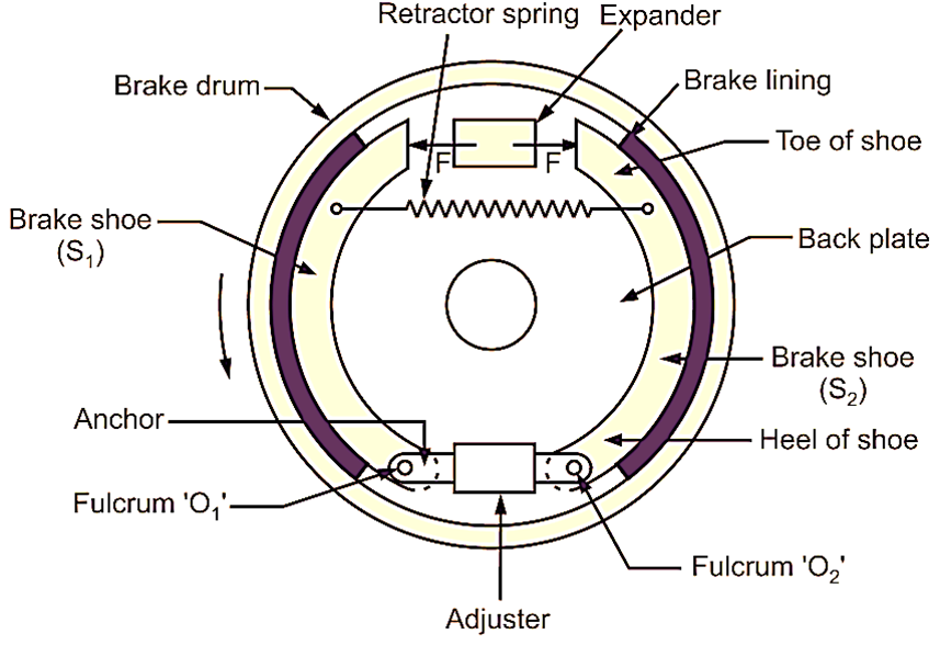
Correct drum brake geometry is important in order to ensure that: · Brake linings wear evenly. · Brake output torque is appropriate to the application. Figure 1 The major drum brake components . Figure 1 shows a typical arrangement of the shoes and other stationary components in a drum brake. The whole assembly is mounted on the back plate.
Putting on the Brakes TOC Automotive College
In this article, we will take a closer look at the drum brake parts diagram, highlighting the key components and their functions. One of the main components of a drum brake system is the brake drum itself. The brake drum is a cast-iron cylinder that is mounted on the wheel hub. When the brake pedal is pressed, the brake shoes are forced against.
How Drum Brake Works? It’s Advantages & Disadvantages
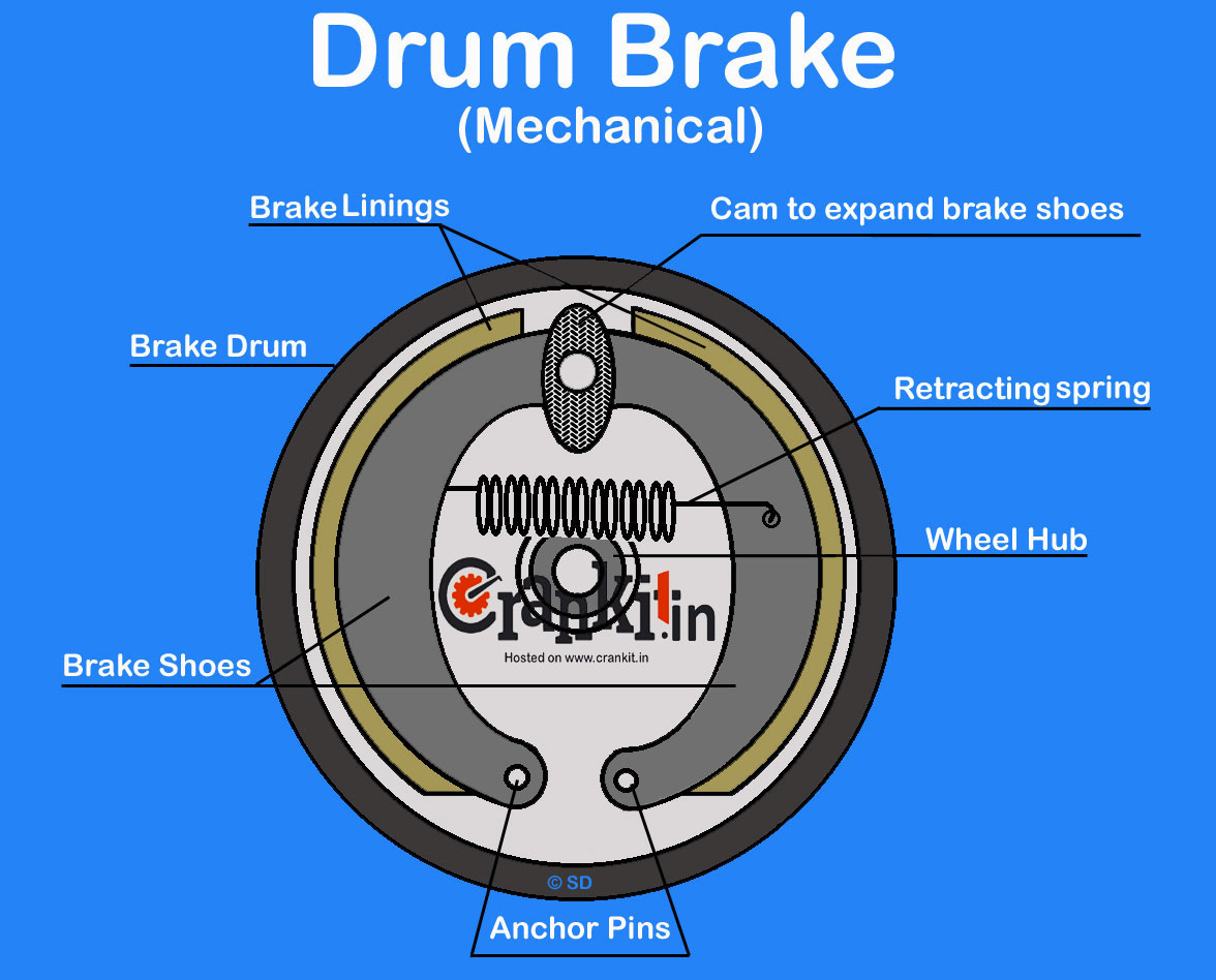
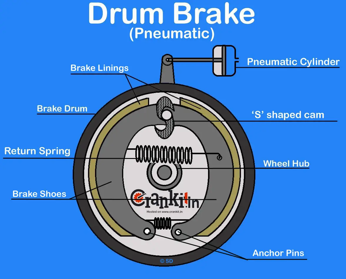
Working, Diagram, Construction & Applications Drum brakes are widely used in different applications. They are the cheapest as compared to other types of brakes. Drum brake consists of a rotating brake drum mounted on the wheel and two semi-circular brake shoes attached on a stationary back plate.

Structure And Working Principle Of Drum Brake News TAIZHOU SHUANGYI
A ratchet on the handbrake lever keeps the brake on once it is applied. A push button disengages the ratchet and frees the lever. On drum brakes, the handbrake system presses the brake linings against the drums. Engine Block 18 minutes. Stop wasting time on YouTube and get serious!
Drum Brakes Diagram
The brake drum is machined to slip over the end of the axle's wheel studs and surround the entire brake system. When you're driving, it rotates at the same rate as the car's wheel. So when you hit that brake pedal, the brake shoes push outward against the spinning brake drum. The friction generated slows the wheel down, thereby making.
Engineering Inspiration The Geometry of Drum Brakes
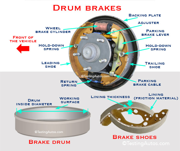
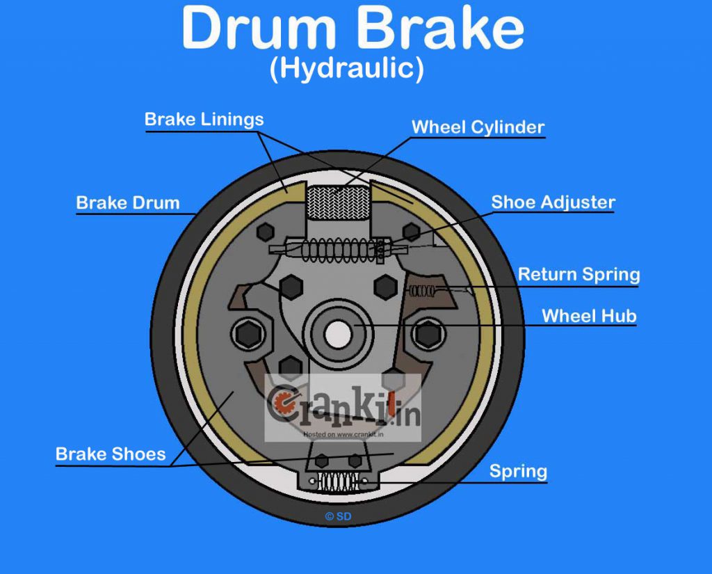
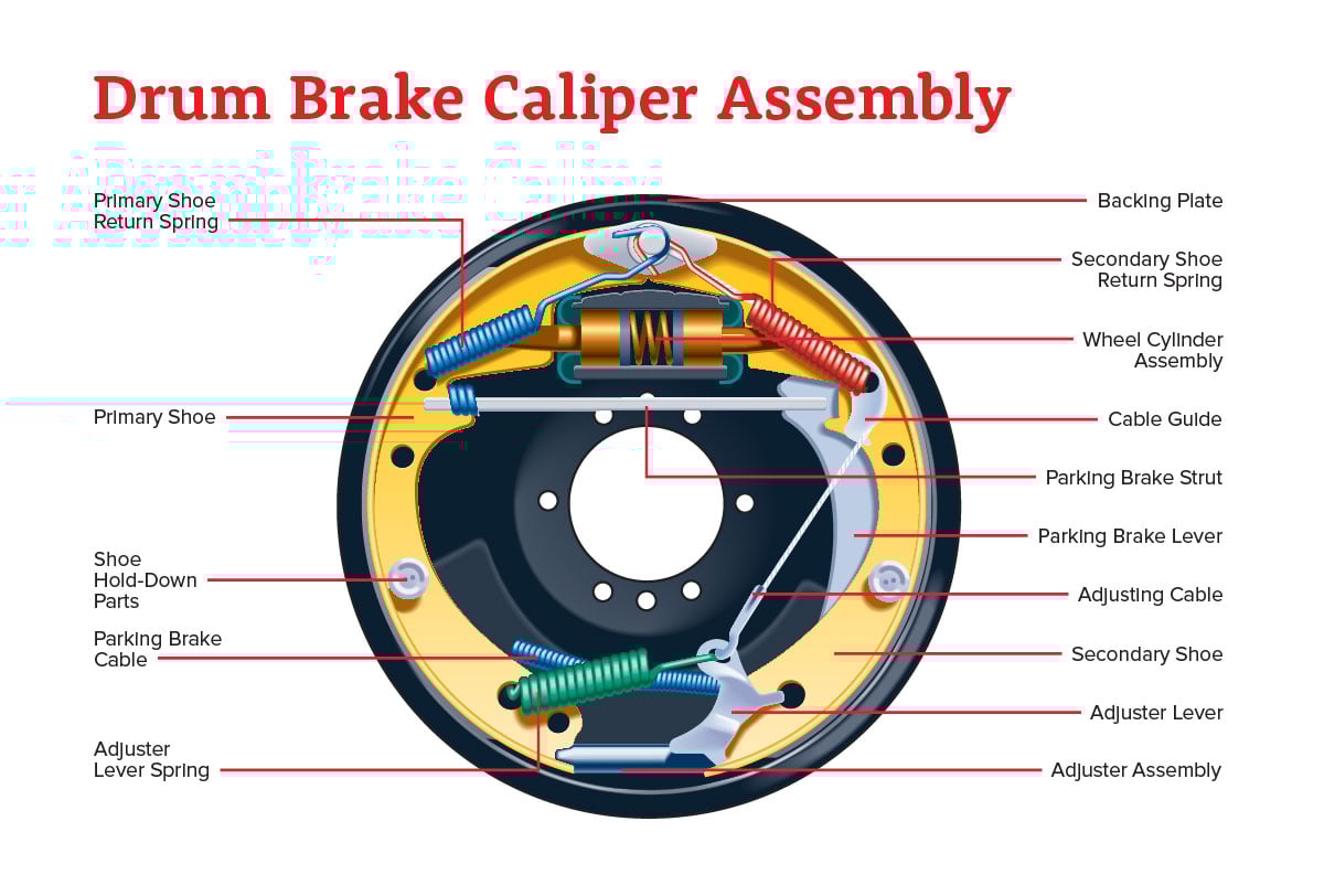
Drum Brake Diagram Explanation Here you can see a clear explanation of the different kinds of parts inside the drum brake systems. We can explain all of these parts. Wheel Brake Cylinder: Two-Wheel Brake Cylinder is the system that the hydraulic fluid that comes to the brake system.
Drum Brake Diagram & Working Explained
It sets front to rear braking ratio. That is, it lets the front brakes have a little more pressure than the rears. This is to make the brakes stop at the same time, with the fronts locking up just ahead of the rears. Your front brakes do most of the stopping. 3. It does the job of a RESIDUAL PRESSURE VALVE. It keeps 10 PSI in the drum brake lines.
Drum Brakes Diagram
The working principle of a drum brake is pretty straightforward: As the driver presses the brake pedal, the brake booster (vacuum servo) intensifies the force and the master cylinder converts it into hydraulic pressure (oil pressure). Using a brake oil-filled tube, the pressure is transferred to the brakes on the wheels (brake fluid).
How Drum Brake Works? It's Advantages & Disadvantages CarBikeTech
A brake drum is a rotating, cylinder-shaped part that exerts pressure outwardly on a set of shoes or pads to produce friction. Drum brakes are brakes where the shoes press against the inner surface of the drum. When shoes contact the outside of the drum, it is commonly referred to as a clasp brake.

Car Drum Brake Diagram
Simplified free body diagram for simplex drum brake by Mahmoud [13] | Download Scientific Diagram Fig 1 - uploaded by Mohd Nurhidayat Content may be subject to copyright. Simplified free body.

Drum Brakes Diagram
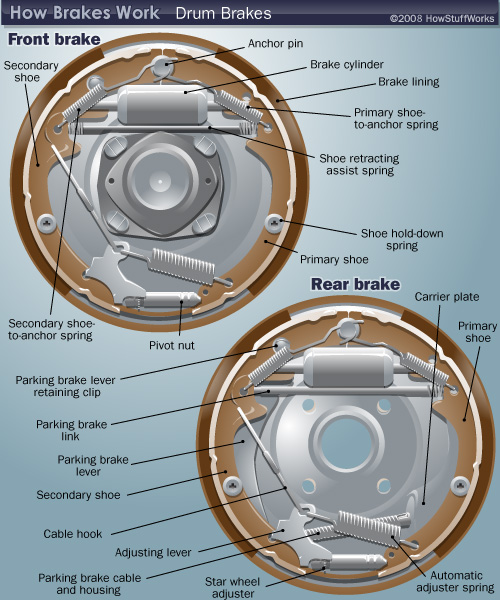
Drum Brake Diagram - How Drum Brakes Work | HowStuffWorks How Drum Brakes Work Prev NEXT By: Karim Nice Drum Brake Diagram Now let's put it all together. The drum brake diagram below shows how all the parts of the brake work together. For more brake topics and links to related auto articles, check out the links below.
Drum brake and Disc Brake Pros and cons
Last updated on 03/08/2022 (Image/Wayne Scraba) Drum brakes were standard equipment for decades. Even high-powered muscle cars were equipped with drum brakes on at least one axle. Many were equipped with drums on the front too. Drums can fade. They're affected adversely by water. They require adjustment periodically.

Drum Brake Diagrams 101 Diagrams
1. Backing plate: Provides a solid base for other components in the drum brake attached to the axle sleeve. 2. Brake drum: Bolted to the wheel hub and spins with the wheel. Often made of cast iron, and is resistant to heat and wear.
Cat Brakes
The first step to replacing your Chevy drum brakes is to remove the wheel. Once you've removed the wheel, you'll want to pull off the lug nuts holding the wheel onto the hub. Then, you'll want to take off the brake caliper. Next, you'll want to disconnect the brake lines from the master cylinder. After this, you'll want to remove the brake line.
Drum Brake Diagrams 101 Diagrams
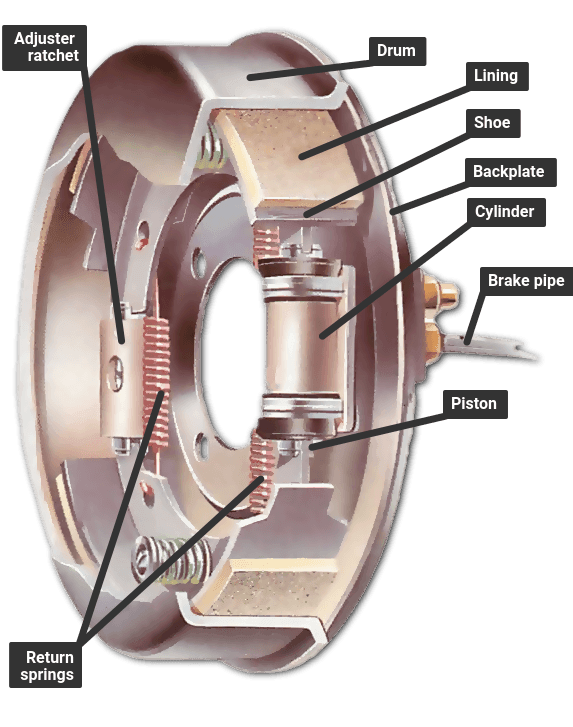
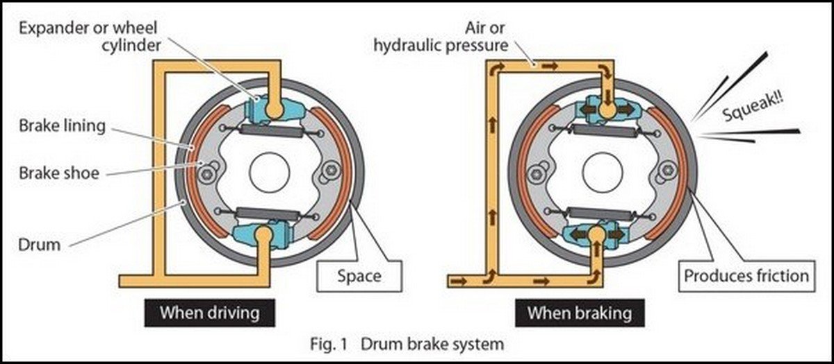
Diagram of Drum Brakes Drum brakes are a brake system with brake drums (rotor) that rotate with the wheels. Inside each drum are brake shoes fitted with brake linings (friction material). Pistons (pressure mechanism) press against the drums from the inside to generate braking force, thus making it possible to decelerate and stop the vehicle.
Drum Brakes Diagram
1 Put on an asbestos respirator. The work you're about to do involves finely-ground brake dust or asbestos dust, and breathing it can be extremely hazardous to your health. Get a mask that's designed for the job of filtering asbestos, not a simple paper one you might use in a shop. Send the kids and pets away, too.